

J
Jay JenkinsJul 29, 2025
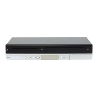
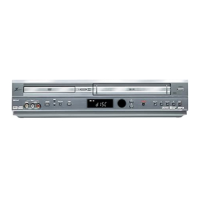
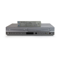
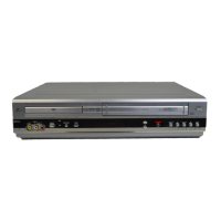
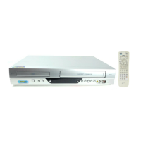
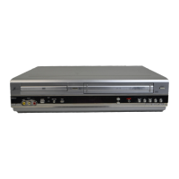
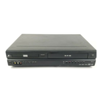
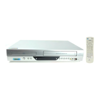
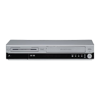
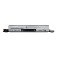
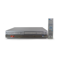
What to do if Zenith DVD VCR Combo will not record even though the timer is set?
- PPhillip SchmidtJul 29, 2025
If your Zenith DVD VCR Combo isn't recording despite the timer being set, make sure you've loaded a recordable disc or tape. Also, check that 'Disc Protect' is disabled in the Disc menu. If the disc is full with 99 titles, delete some to free up space.