3-11
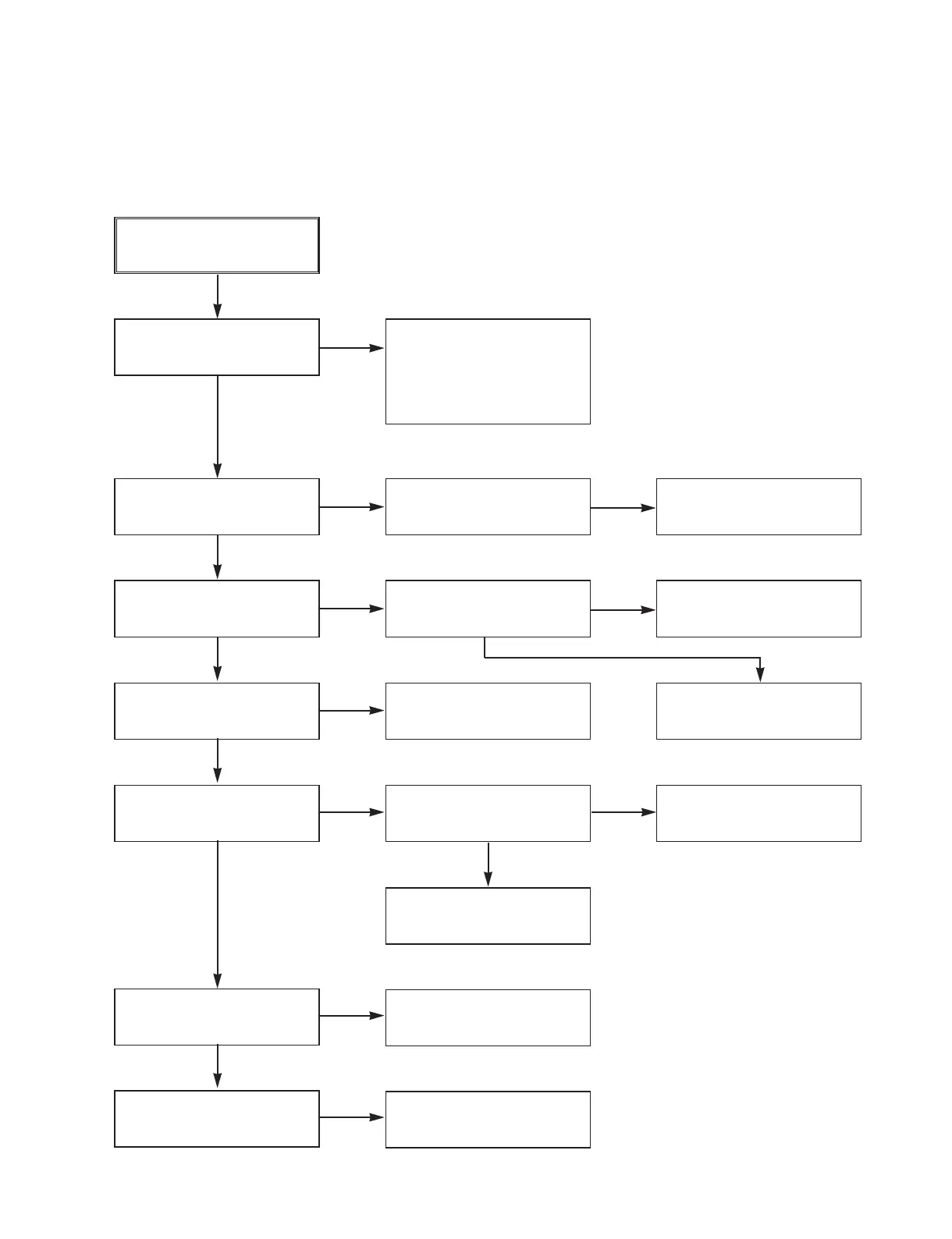
5. Y/C CIRCUIT
(1) No Video in EE Mode,
No Video in EE Mode
Does the Video signal
appear at IC301
Pins28, 30, 32?
Is REG 5.0V applied to
IC301Pins23, 44, 45, 52, 68,
77?
Does the Video signal
appear at IC301 Pin26?
Does the Video signal
appear at IC501 Pin52?
Does the Video signal
appear at PMD02 Pin7?
Does the Video signal
appear at the PMD02
Pin5?
Does the Video signal
appear at the JK602
Video Out Jack?
Check the REG 5V Line.
(Power Circuit)
Is I
2
C BUS signal applied to
IC301 Pins53, 54, 55?
Replace IC301.
Check the path of the sig-
nal between IC301 Pin 26
and IC501 Pins50, 52.
Is there REG12 on the
plus terminal of C653?
Check the REG 12V Line.
(Power Circuit)
Check the Q605
(Video Buffer)
Check the VDR
Module
Check the IC601 and
Video Out Line
Check the System Circuit.
(Refer to ‘SYSTEM I
2
C BUS
CHECK Trouble Shooting’)
YES
YES
YES
YES
YES
YES
YES
YES
NO
NO
NO
NO
NO
NO
NO
NO
Check the REG 5V Line.
(Power Circuit)
NO
NO
Check VDR Video Input
(PMD02 Pin 5), Tuner Video
Input (TU701 Pin24), Line
Video Input (IC602 Pins 1, 3,
5, 7), respectively.
VCR ELECTRICAL TROUBLESHOOTING GUIDE