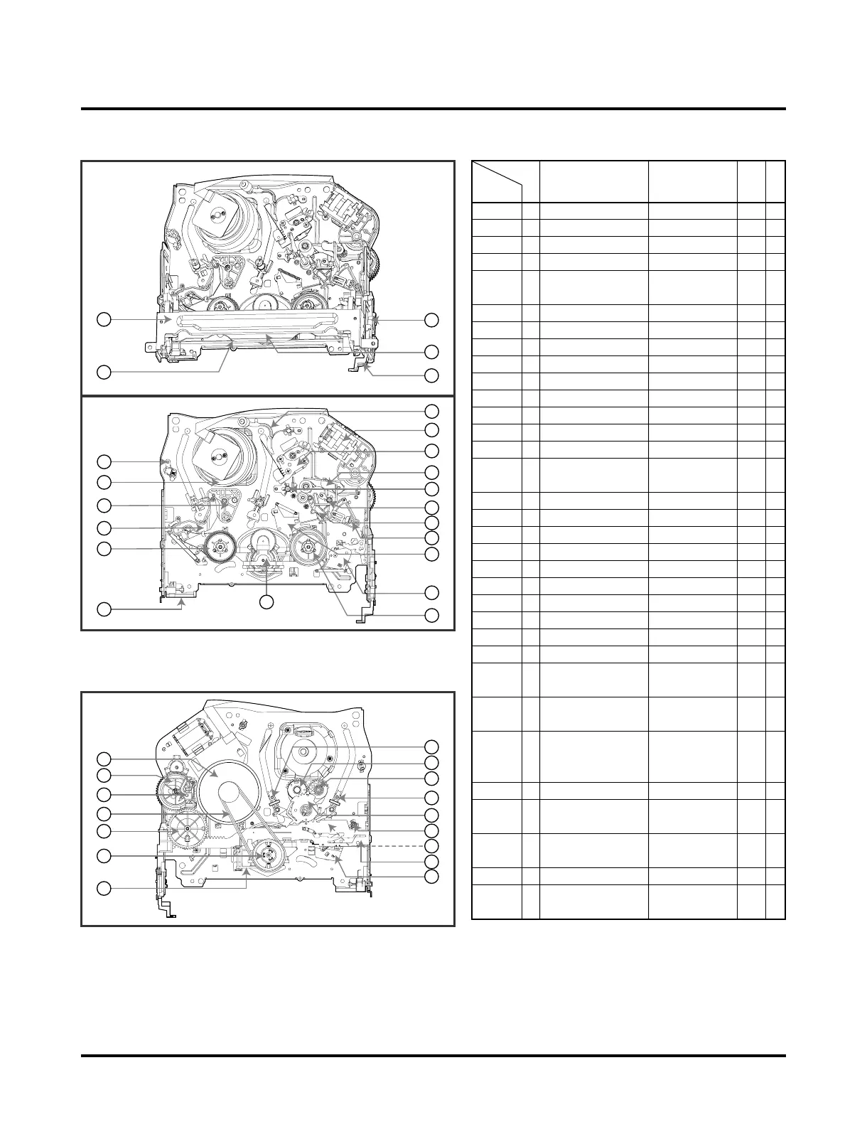
NOTE: When reassembly perform the
procedure in the reverse order.
1 Drum Assembly 3 Screw A-1 T
2 Top Plate Assembly 2 Hook A-2 T
2 3 CST Holder Assembly Chassis Hole A-2 T
2 4 Door Opener Chassis Hole A-2 T
5 L/D Motor Bracket 3 Hook A-2 T
Assembly
2,3,4 6 F/L Gear Rack 1 Hook, Chassis Hole A-2 T
2,3,4,6 7 F/L Arm Assembly Chassis Hole A-2 T
8 S/W Lever Assembly 1 Hook A-2 T
9 Cleaner Arm Assembly Chassis Embossing A-3 T
10 F/E Head Chassis Embossing A-3 T
11 A/C Head Base Assembly 1 Screw A-3 T
2,3 12 T Brake Assembly 1 Hook A-4 T
2,3 13 RS Brake Assembly 1 Hook A-4 T
2,3 14 Tension Arm Assembly 2 Hook A-4 T
2,3,12,13, 15 S Reel / T Reel A-4 T
14
16 P4 Base Assembly Chassis Embossing A-5 T
17 Lid Opener Chassis Embossing A-5 T
17 18 Pinch Arm Assembly Shaft A-5 T
17 19 T/up / Arm T/up Lever 1 Hook A-5 T
17,18 20
Capstan Belt /Capstan Motor
3 Screw A-6 B
21 F/R Lever Locking Tab A-6 B
20, 21 22 D35 Clutch Assembly Washer A-6 B
23 Capstan Brake Assembly Locking Tab A-6 B
24 Drive Gear / Cam Gear Washer/Hook A-7 B
25 Sector Gear 1 Hook A-7 B
20,21,23, 26 Slider Plate Shaft Guide A-7 B
24,25
20,21,23, 27 Tension Lever 1 Hook A-7 B
24,25,26
2,3,14,20, 28 Spring Lever Locking Tab A7 B
21,25,23,
24,26
25 29
P2 Gear Assembly/P3 Gear Assembly
Boss A-8 B
2,3,14,25, 30
P2 Base Assembly/P3 Base Assembly
Chassis Slot A-8 B
29
2,3,14,25, 31 Loading Base 1 Screw A-9 T
29
2,3,14 32 Tension Base Chassis Embossing A-9 B
2,3,20,21, 33 Idler Arm Jog Assembly Locking Tab A-9 T
22
Starting
No.
Procedure
Part Fixing Type
Fig-
ure
1) When reassembling, confirm Mechanism and Mode
Switch Alignment Position (Refer to Page 4-14)
2) When disassembling, the Parts in the "Starting No."
colum should be removed first.
R: Top, B:Bottom