DECK MECHANISM ADJUSTMENT
4-13
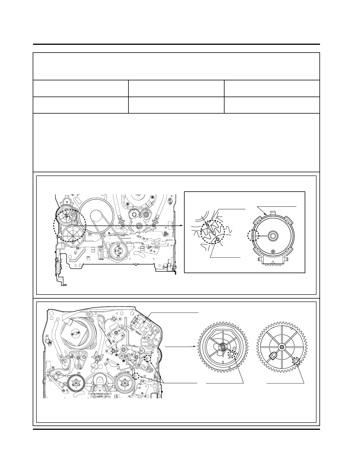
Purpose:To determine if the Mechanism is in the correct position, when a Tape is ejected.
1. Mechanism Alignment position Check
1) Turn the Power S/W on and eject the Cassette by press-
ing the Eject Button.
2) Remove the Top Cover and Top Plate Assembly, visual-
ly check if the Cam Gear Hole is aligned with the
Chassis Hole as below Fig. C-2.
3) If not, rotate the Shaft of the Loading Motor Clockwise or
Counterclockwise until the Alignment is as shown below
in Fig. C-2.
4) Remove the Screw which attaches the Deck Mechanism
and Main Frame, confirm the Cam Gear is aligned with
the Drive Gear as shown below in Fig. C-1 (A).
5) Confirm if the Mode S/W on the Main P.C. Board is
aligned as shown below in Fig. C-1 (B).
6) Remount the Deck Mechanism on the Main P.C. Board
and check each operation.
Test Equipment/ Fixture
• Blank tape
Test Conditions (Mechanism
Condition)
• Eject Mode (with Cassette ejected)
Check Point
• Mechanism and Mode Switch Position
Fig. C-1
Fig. C-2
CHECK DIAGRAM
BOTTOM VIEW
TOP VIEW
Gear Cam (o) and Gear Drive (o) groove alignment