Purpose: To insure that the Tape passes accurately over the Audio and Control Tracks in
exact alignment in both the Record and Playback Modes.
Test Equipment/ Fixture
• Blank Tape
• Screw Driver (+) Type 5mm
• Play the blank tape
Test Conditions (Mechanism Condition)
Adjustment Point
• Tilt Adjustment Screw (C)
• Height Adjustment Screw (B)
• Azimuth Adjustment Screw (A)
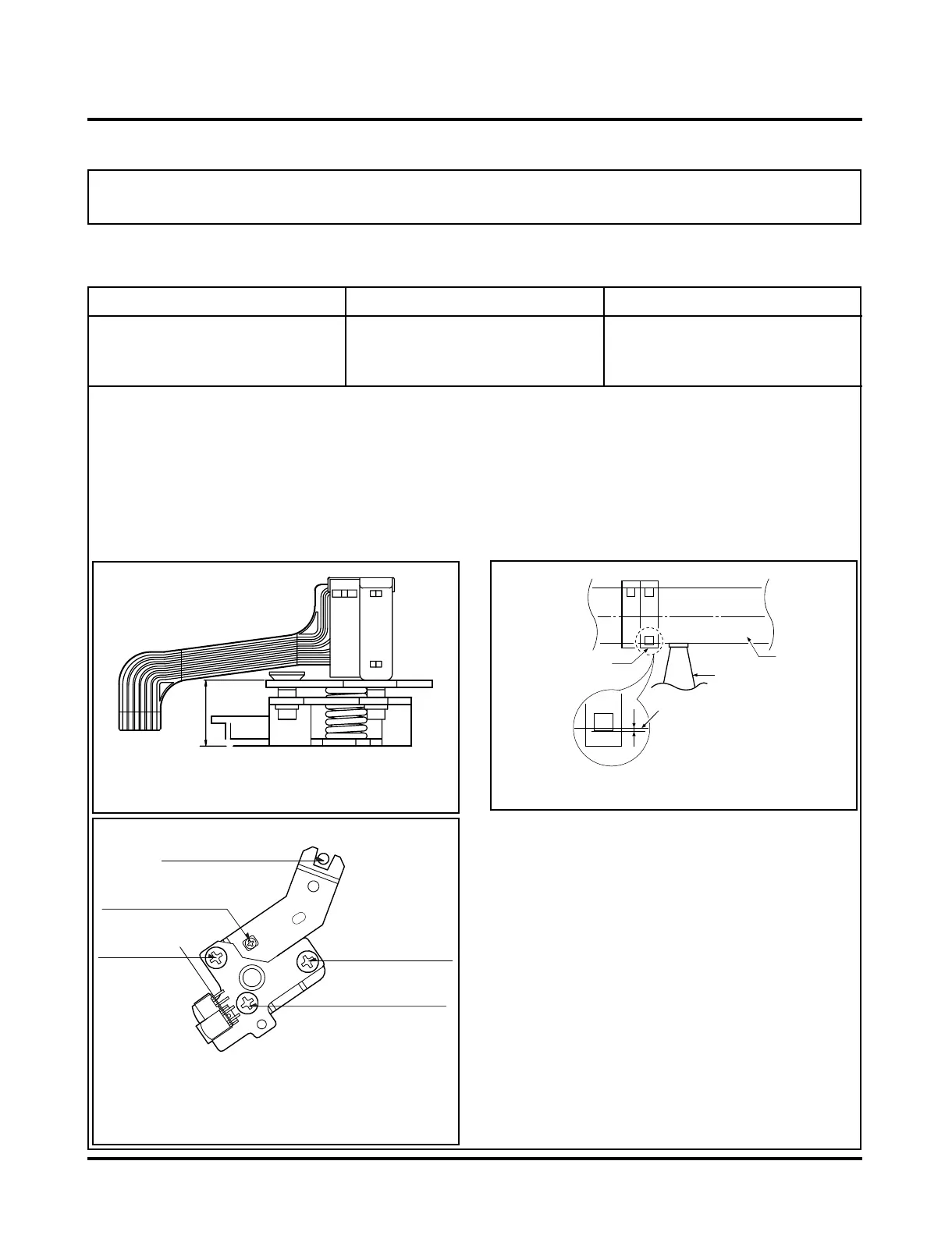
Fig. C-5-1
A/C Head Base
Fig. C-5-2
Height Adjustment
Screw (B)
Tilt Adjustment
Screw (C)
Azimuth Adjustment
Screw (A)
X-Value Adjustment
Hole
Fixed Screw
Fig. C-5-3
A/C Head
Tape
Tape
0.2~0.25mm
P4
5-1. Preliminary Adjustment (Height and Tilt Adjustment)
Perform the Preliminary Adjustment, when there is no Audio Output Signal with the Alignment Tape.
1) Adjust the A/C Head Base Assembly as shown Fig. C-5-
1 by using the Height Adjustment Screw (B).
2) Play a Blank Tape and observe if the Tape passes accu-
rately over the A/C Head without the Tape Curling or
Folding.
3) If Folding or Curling occurs adjust the Tilt Adjustment
Screw (C) while the Tape is running to resemble Fig. C-
5-3.
4) Reconfirm the Tape Path after playback of approximate-
ly 4~5 seconds.
Ideal A/C head height occurs when the tape runs between
0.2~0.25mm above the bottom edge of the A/C head core.
NOTE
Adjustment Procedure/Diagrams
A/C Head Assembly