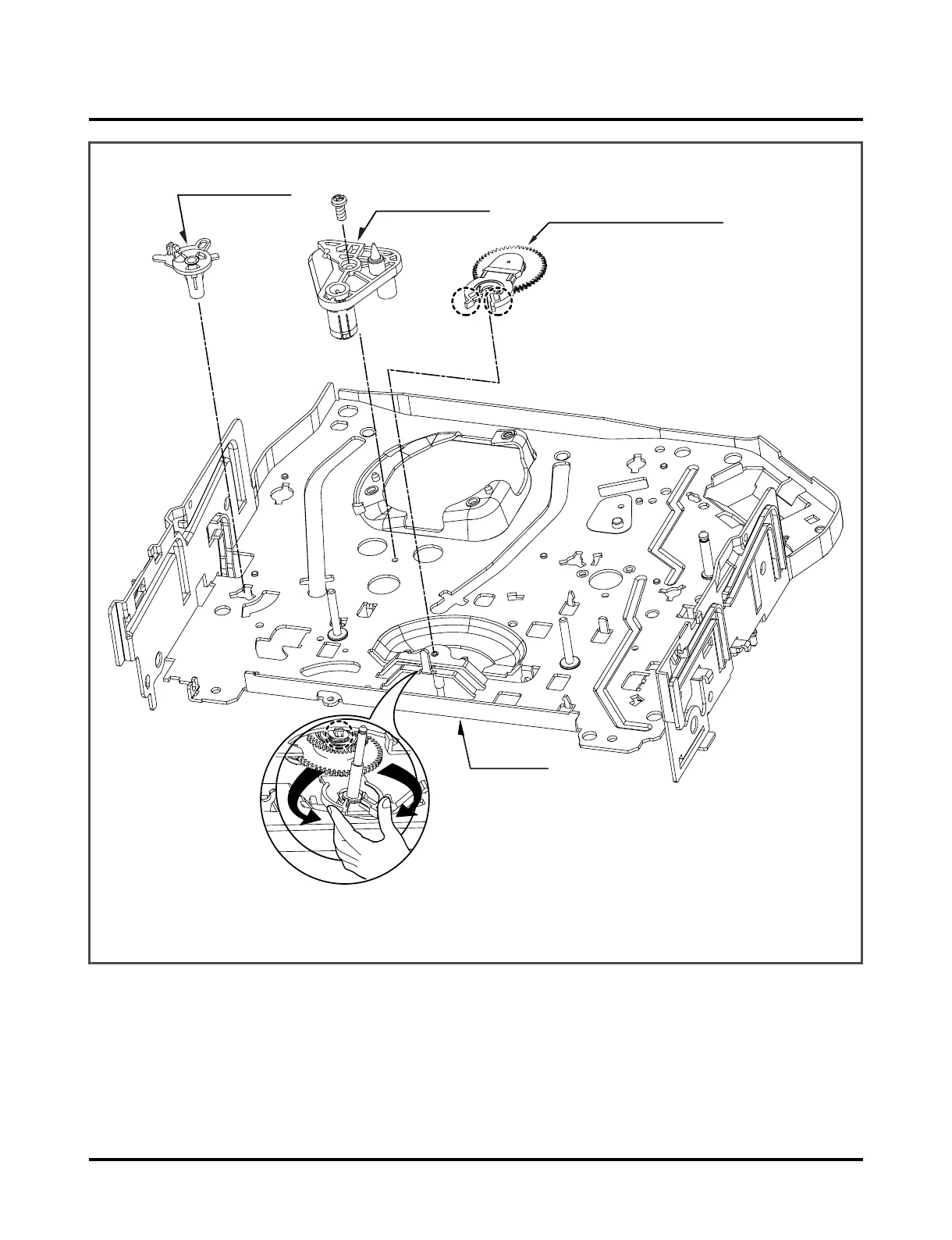
Fig. A-9
31. Loading Base (Fig. A-9-1)
1) Remove the Screw (S7).
2) Lift the Loading Base up.
32. Tension Base (Fig. A-9-2)
1) Remove the (A) portion of the Tension Base from the
Embossing of the Chassis.
2) Turn the Tension Base counterclockwise and lift it up.
33. Idler Arm Jog Assembly (Fig. A-9-3)
1) Pinch (B) and (C), as shown in Fig. A-9-3.
2) Lift the Idler Arm Assembly up.
When disassembling, be careful not to catxh part (D) on the
Chassis (see inset).
NOTE
(Fig. A-9-1)
(Fig. A-9-2)
(Fig. A-9-3)