3-3
ELECTRICAL ADJUSTMENT PROCEDURES
1. Servo Adjustment
1) PG Adjustment
• Adjustment And Specification
• Test Equipment
a) OSCILLOSCOPE
b) NTSC MODEL : NTSC SP TEST TAPE
MODE
PLAY
• Adjustment Procedure
a) Insert the SP Test Tape and play.
b) Connect the CH1 of the oscilloscope to the H/SW and CH2 to the “VCR VIDEO” TP for the VCR.
c) Trigger the mixed Combo Video Signal of CH2 to the CH1 H/SW, and then check the distance (time dif-
ference), which is from the selected A(B) Head point of the H/SW(W5D1, W5D2) signal to the starting
point of the vertical synchronized signal, to 6.5H ± 0.5H (412µs, 1H=63.5µs).
• PG Adjustment Method
a-1) Playback the SP standard tape
b-2) Press the “ENTER” key on the Remote controller and the “REC” key on the Front Panel at the same
time, then it goes into Tracking initial mode. < Digitron[ - - ] >
c-3) Repeat the above step(No.b-2), then it finishes the PG adjusting automatically. < Digitron[ PG ] >
d-4) Stop the playback, then it goes out of PG adjusting mode after mony the PG data.
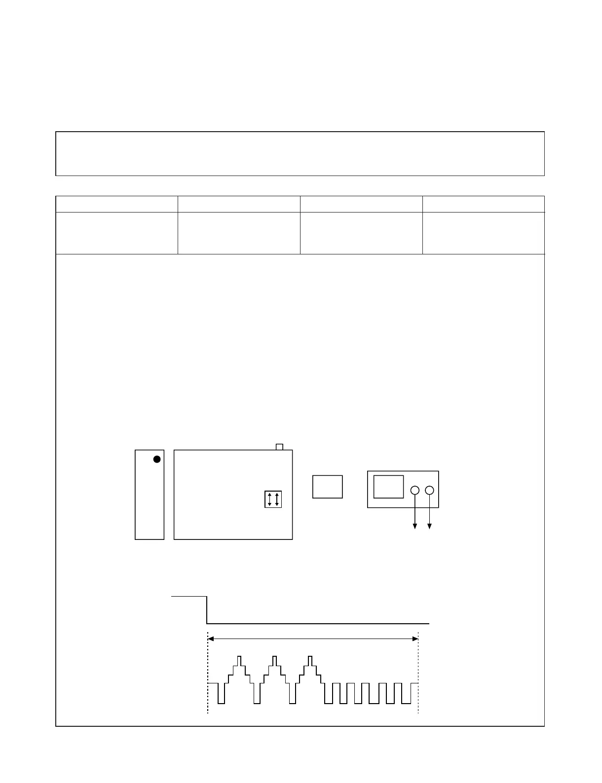
• CONNECTION
• WAVEFORM
V.Out
H/SW(W5D1, W5D2)
R/C TRK JIG KEY 6.5 ± 0.5H
MEASUREMENT POINT ADJUSTMENT POINT SPECIFICATION