3-8
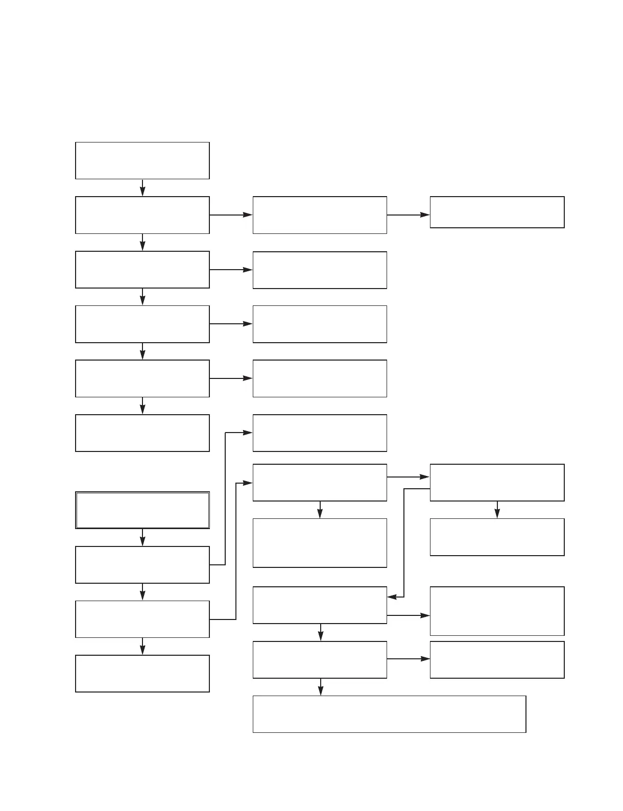
3. SERVO CIRCUIT
(1) Unstable Video in PB MODE
Does the Noise level of the
screen change
periodically?
Do the CTL pulses appear
at IC501 Pin97?
Is the height adjustment of
the CTL Head accurate?
Check Deck Motor.
Readjust the height of the
CTL Head.
Replace IC501.
Refer to “When the Y signal
doesn’t appear on the
screen in PB Mode”.
Confirm the CFG
waveform at IC501 Pin87?
On tracking, do the CTL
pulses move?
Does the Video Envelope
waveform appear at IC501
Pin9?
Replace IC501.
YES
YES
YES
NO NO
NO
NO
NO
(2) When the Drum Motor
(2) doesn’t run.
Do the DFG Pulses appear
at PMC01 Pin11?
Replace the Cap M.
Are the foil patterns and
the Components between
IC501 Pin 90 and PMC01
Pin11 shorted?
Replace IC501.
Refer to “(2)
No 12VA of Power section”
Do the Drum PWM Pulses
appear at IC501 Pin76?
Are the foil patterns and
the Components between
IC501 Pin76 and PMC01
Pin12 shorted?
Do the DFG Pulses appear
at IC501 Pin90?
Do the Drum PWM Pulses
appear at IC501 Pin76?
Are the connecting patterns and the Components
between IC501 Pin76 and PMC01 Pin12 shorted?
When the Drum Motor
doesn’t run,
Does 12V appear at
PMC01 Pin8?
Does 2.8V appear at
PMC01 Pin12?
Check the connector
(PMC01) and the Drum
Motor Ass’y.
NO
YES
YES
YES
NO
NO
NO
NO
NO
YES
YES
YES
VCR ELECTRICAL TROUBLESHOOTING GUIDE