SIMPLICITY PLUS INSTALLATION MANUAL
Approved Document No: GLT.MAN-107 PAGE 17
Issue 3.16 Author: NRPJ Date: 21/09/2017
Cconnections for a ceiling mount version remote LED Connections for a wall mount version remote LED
7.1.10 Isolator Base
7.2 MAXIMUM LOOP LENGTH RECOMMENDATIONS
With an addressable system, some care must be taken when calculating the appropriate cable gauge for the system.
The main limitation is that during an alarm condition (maximum current draw), the voltage at all devices must be at least
17 Volts with at least 5V of superimposed data signal.
The exact calculation equations are beyond the scope of this manual, because of the distributed load of the sounders on
the loop, but the following table gives a rough guide for maximum cable lengths at various current loads for 3 different
cable gauges
Maximum Loop Current (in Alarm) 500 mA 400 mA 300 mA 200 mA
1.0mm CSA cable 500m 625m 830m 1250m
1.5mm CSA cable 750m 930m 1250m 1870m
2.5mm CSA cable 1000m 1250m 1660m 2000m
EG. A system with a maximum load of 300mA using 1.5mm cable can have a maximum loop run of 1250m end to end.
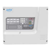
7.3 SETTING THE DEVICE ADDRESS (DETECTORS, CALL POINTS & SOUNDERS)
The device address is set with a dip switch on the rear of the device.
1 7
65
43
2
8
ON
The address setting is binary, with the ON position being binary
0 , and the OFF position being binary 1.
On a Simplicity system, a MKII Protocol device must ALWAYS
have Switch 8 set to the ON position.
If you are not familiar with binary, check the table in section 7.4
or use the following rule:
Switch 7 off = add 64,
Switch 6 off = add 32,
Switch 5 off = add 16,
Switch 4 off = add 8,
Switch 3 off = add 4,
Switch 2 off = add 2,
Switch 1 off = add 1.
The example shown would be:
switches 6, 4 & 1
=32 + 8 + 1 = Address 41
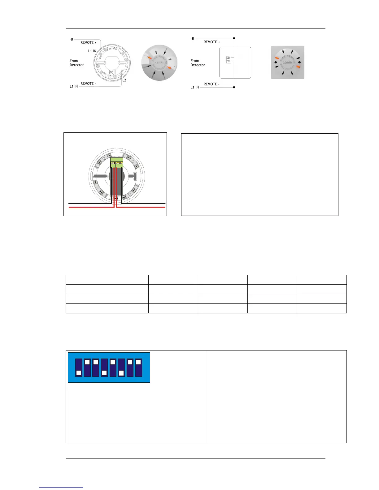
Fyreye MKII Loop Isolator Base
MKII-IB
L
2
Note that on the Fyreye Loop Isolator Base, the loop wiring connects
to the terminal block on the PCB and NOT to the Base Spring Screws.
The terminals are marked + & - in, and +,- &- out.
The second –ve contact can be used during commissioning to check
the loop integrity.
(Connect the –in to the spare – out. Repeat for all isolators. Measure
–ve line resistance with a DVM. Return the –in cable to its original
terminal block when tests completed.)