SIMPLICITY PLUS INSTALLATION MANUAL
Approved Document No: GLT.MAN-107 PAGE 45
Issue 3.16 Author: NRPJ Date: 21/09/2017
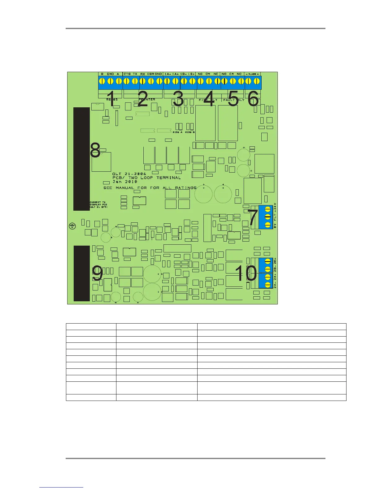
21. PCB TERMINATION CONNECTIONS
21.1 SIMPLICITY PLUS CIE TERMINATION PCB
21.2 CONNECTIONS
CONNECTION NO DESCRIPTION USE
1 RS 485 REPEATER To link to addressable repeater
2 RS232 PRINTER Serial port. Link to printer or TCP-IP reporting module
3 ADDRESSABLE LOOP 1 Connect to detector wiring: loop 1
4 FIRE RELAY Volt free relay. Operates on any alarm
5 FAULT RELAY Volt free relay – normally energised. Operates on any fault
6 CLASS CHANGE Remote input to operate fire alarm panel sounders
7 24V & FAULT FROM PSU Power & power supply fault connection to power supply
8 34 WAY RIBBON CABLE TO DISPLAY Connects Loop 1 signals & general signals to display PCB
9
10 WAY RIBBON CABLE TO DISPLAY Connects Loop 1 signals to display PCB
(on 2 loop simplicity only)
10 ADDRESSABLE LOOP 2 Connect to detector wiring: loop 2 (on 2 loop simplicity only)