SIMPLICITY PLUS INSTALLATION MANUAL
Approved Document No: GLT.MAN-107 PAGE 46
Issue 3.16 Author: NRPJ Date: 21/09/2017
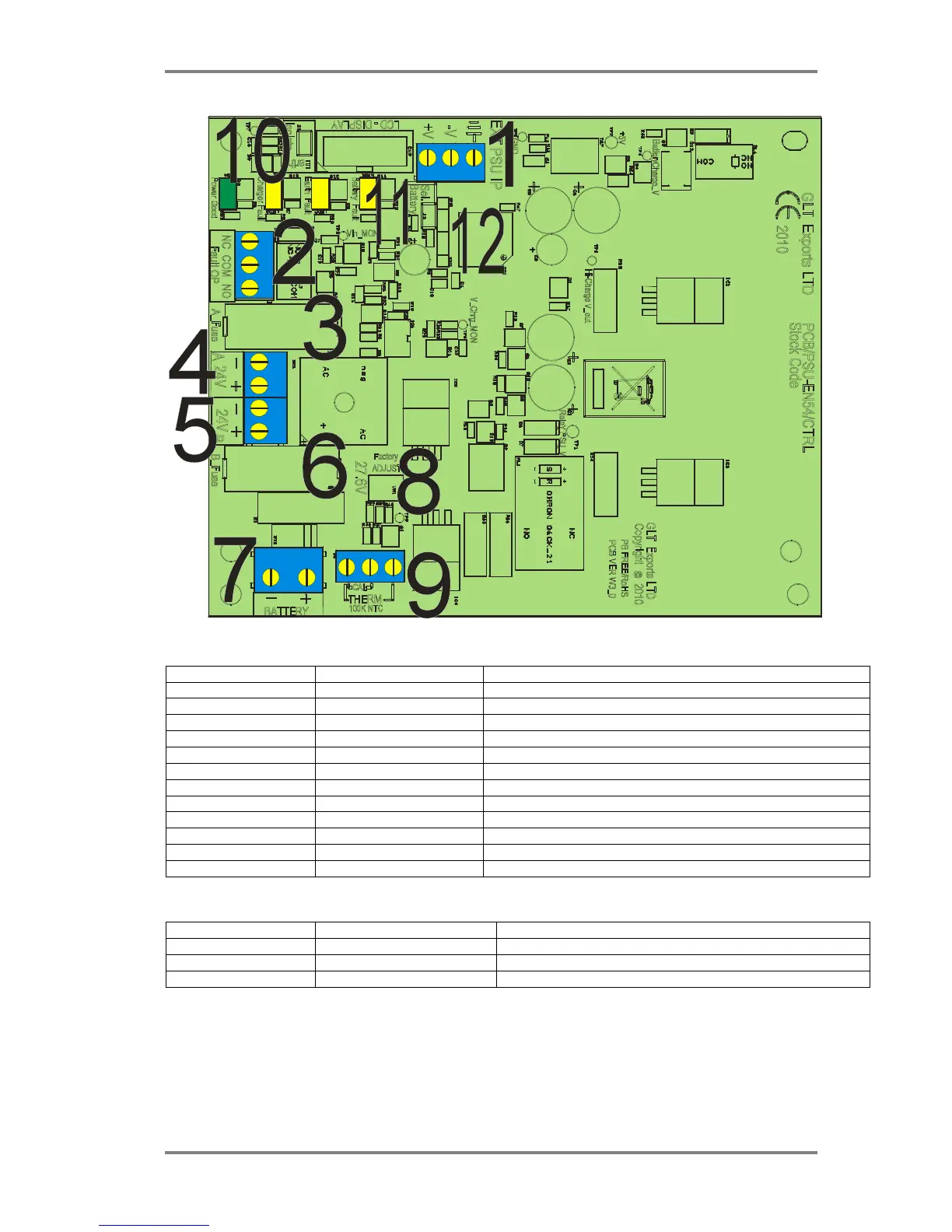
21.3 SIMPLICITY PLUS POWER SUPPLY PCB
21.4 SIMPLICITY PLUS POWER SUPPLY CONNECTIONS
CONNECTION NO DESCRIPTION USE
1 EXT PSU IP External Power input from Switch Mode cage
2 FAULT OP Volt free fault relay, normally energised
3 A-FUSE Fuse for the first 24V output
4 24V A Connection for the first 24 V output
5 24V B Connection for the second 24 V output
6 B-FUSE Fuse for the second 24V output
7 BATTERY Battery connection. 2 x 12V SLA batteries wired in series
8 FACTORY ADJUST Charger adjust pot. DO NOT ADJUST
9 THERM Battery charger temperature compensation thermistor
10 EARTH ISOLATE Jumper link to enable / disable earth fault reporting
11 SEL. BATTERY Link to put charger in calibration mode from power up.
12 CN2 / CN3 ISP programming connector
21.5 SIMPLICITY PLUS POWER SUPPLY FUSES
FUSE NO DESCRIPTION RATING
IN LINK WIRE Battery Fuse 5.0A time delay 5 x 20mm glass
FS1 Supply Fuse A 1.0A time delay 5 x 20mm glass
FS2 Supply Fuse B 1.0A time delay 5 x 20mm glass