Page 10 of 28 801314 v3.05 09.20 HT BC Commercial Instructions
Before Installation
Before installing ensure that the following have been provided at the
Installation site:
•
Review all the technical specifications.
•
Ensure the underbench can support the product weight when full of water,
(allow an extra 5kg when full. )
•
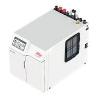
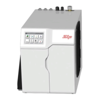
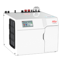
Sufficient space in the cupboard to install the Command Centre in accordance with these Installation
Instructions. Refer to technical specification for dimensions. Make allowance for a booster heater and
/ or water softener if required. Refer to section 3 & 4, for Installation instructions.
•
For Zip HydroTap 160/125 &160/175 models, a 220-240V, 10A AC power outlet will be required. For
Zip HydroTap 240/175 models, two 220-240V, 10A AC power outlets will be required (one power
outlet for the Zip HydroTap and the other for the Booster heater).
NoteNote: Check all cable and hose lengths against inlet /outlet positions before proceeding
(See section 5 for general layout).
•
A potable water supply connection with isolating valve inside the cupboard within reach of the braided
hoses and positioned so that the connection point and the stop cock will not be obstructed when the
Command Centre is installed.
•
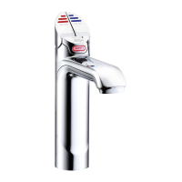
For the mains pressure All-in-One tap, an external hot and cold water supply will be required.
•
If an external filtration or water softening device is required, then it is important to allow extra space
for these items.
•
A cold water supply with a minimum working pressure of 150kPa (200kPa when a booster and /or
filter softener is fitted) and a maximum working pressure of 700kPa connected via an isolation valve.
•
The fitting of an air flow duct, attached to the right hand side of the Command Centre, requires a
rectangular cut size of 284mm x 45mm, to provide adequate warm air displacement. See section 2.
•
The appliance must be placed with its base in a horizontal position.
IMPORTANT!
Do not proceed with the installation if these requirements are not met.
Special Tools Required:
In addition to normal tools, the following will be required:
For the standard and Mixer taps:
•
35mm diameter sheet metal hole punch for sink tops (not supplied)
•
35mm diameter hole saw for timber bench tops (not supplied)
•
Nut runner tube spanner (supplied) for fixing tap assembly.
For the All-In-One tap:
•
50mm diameter sheet metal hole punch for sink tops (not supplied)
•
50mm diameter hole saw for timber bench tops (not supplied)
•
Nut runner tube spanner (supplied) for fixing tap assembly.
 Loading...