Page 12 of 28 801314 v3.05 09.20 HT BC Commercial Instructions
Ventilation
= =
max 43
314.00
12.00
12.00
285.00
12.00
5
326.00
CUT OUT DETAILS
A
A - KICKBOARD CUT-OUT
1. Drill 4 pilot holes Ø12 in corners
2. Finish cut-out using Jigsaw
and Keyhole or Wall Board saw
B - CABINET FLOOR
CUT-OUT
1. Drill two pilot holes Ø12
2. Finish cut-out using Jigsaw
C - CABINET FLOOR
CUT-OUT
1. Drill 4 pilot holes
Ø12 in corners
2. Finish cut-out using Jigsaw
and Keyhole or Wall Board saw
NOTE: Ensure that
Cut-outs 'A' and 'B' are on opposite side of cabinet.
Cut-out 'C' is straight behind 'A'
60.00
B
C
12.00
45.00
284
285.00
12.00
60.00
WALL OR DOOR CUT-OUT
228
12
98
AIR OUTLET CUT-OUT
Min 450mm
For positioning of cut-out C, use the
template marked on the cardboard carton
The following instructions are critical if the vent kit, as supplied, cannot be fitted:
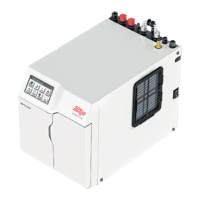
If the kick board vent kit cannot be used then it is important to fit a HydroTap vent tray, which ensures heat
dissipation through the installed vent tray. For high use applications, where the cupboard space temperature
is near 35°C, or higher, an auxiliary fan kit may be fitted. Contact your local service centre for availability.
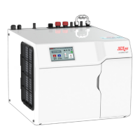
• Vent tray, part no. 93540 (optional accessory)
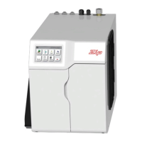
• Dual exhaust fan kit, part no. 93156 (optional accessory)
!
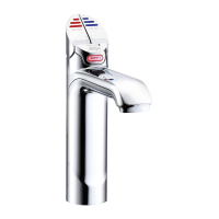
HydroTap G4 on Vent Tray
Vent Tray
Dual Exhaust Fan Kit
Vent Tray Kit
 Loading...