7
EN
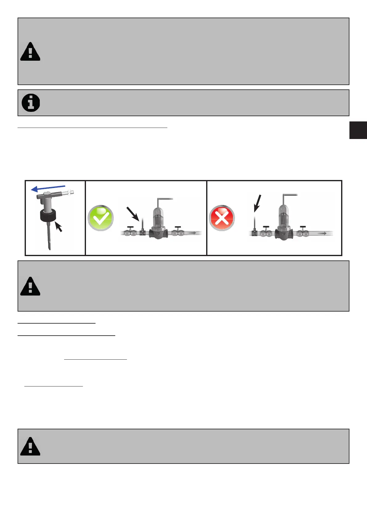
• The cell must always be the last element placed on the pool return pipe (see diagram).
• It is always recommended to install the cell on a by-pass. This assembly is MANDATORY if the ow is in
excess of 18 m³/hour to avoid head loss.
• If you installed the cell on a by-pass, it is recommended to t a check valve downstream from the cell
instead of a manual valve, to avoid any risk of incorrect con gura on which could result in poor circula on
inside the cell.
• If the instruc ons on the loca on and orienta on of the cell are not complied with, there could be a
dangerous build-up of pressurised gas which could cause damage, personal injury or even death.
3
An "AUS" reducer and a black gasket are supplied in the installa on kit. They are intended for 1 1/2" (= 48
mm) pipes. However, the black gasket can be used instead of the original gasket if the pipe is not standardised
(diameter smaller than DN 50 or DN 63).
2.4 Installing the ow switch (Ei² Expert only)
The fl ow switch and its xture collar (Ø50 mm) must impera vely be installed on the piping close to the cell and upstream
from it. Use the threaded adapter and Tefl on tape supplied to install the fl ow switch on its xture collar.
• Cell installed on a by-pass: the fl ow switch must be installed on the cell by-pass between the upstream isola on valve
and the cell itself.
• Cell installed in line: the fl ow switch must be installed just in front of the cell and a er a possible valve.
• A ach the fl ow switch using using the clamping nut only (screw by hand!).
Securing
nut
• Failure to comply with these instruc ons could lead to the destruc on of the cell! The manufacturer cannot
be held liable in this case.
• The ow switch has a direc on for installa on (arrow indicated on it showing the ow direc on for the
water). Make sure that it is correctly placed on its xture collar so that it stops the salt water chlorinator
produc on when ltering is stopped ("No ow" displayed showing the absence of ow, see “5.
Troubleshoo ng”).
2.5 Electric connec ons
2.5.1 Connec ng the control box
The salt water chlorinator can be connected in compliance with the applicable standards in the country of installa on.
Ei² - GenSalt OE: Mandatory connec on: directly coupled to the pool ltra on system (the appliance is only supplied with
power when a ltering cycle is running).
Ei² Expert:
• Preferred connec on: the appliance is permanently plugged in to the power supply (power supply protected by a 30
mA residual current circuit breaker).
• Possible connec on: directly coupled to the pool ltra on system (the appliance is only supplied with power when a
ltering cycle is running).
==> When all connec ons (electrical and hydraulic) have been made, reconnect the mains power supply to power on the
appliance.
• Failure to comply with these instruc ons could lead to the destruc on of the cell! The manufacturer cannot
be held liable in this case.
• Whichever connec on is used, it is mandatory to programme the Ei² Expert opera ng mes (called
"Timers") (see “3.2.5 “SUMMER” and “WINTER” modes and se ng the “Timers””).