2. GAIN SW check
Following the operation “1.”, input sin wave (440Hz/-20dBm) to [INPUT] jack and monitor the
output from [OUTPUT] jack (L/MONO, R) with speakers and oscilloscope.
Make sure that output level changes by switching [-10dBm] and [+4dBm]. Then, output from
[Phones] jack doesn’t change.
*Refer to “Circuit Check Specifications” about the specs of output.
3. OUTPUT LEVEL check
Turn right [LEVEL] volume.
Input audio signal to [AUX IN] jack.
Make sure that outputs level from [PHONE] jack gradually changes by turning around the
[LEVEL] volume of output.
*Insert 32 ohm load.
*Make sure output level changes smoothly by turning volume knob.
*Refer to “Circuit Check Specifications” about the specs of output.
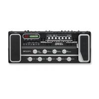
4. VERSION, REVISION, and CRC32 check
Press the [CHANNEL A] key (SW12), and make sure that the [CHANNEL A] key lights up.
Make sure that the LCD is displayed [G9 v1.01 R9031 CRC : 3D78B445]
4/18 present
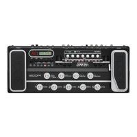
Press the [CHANNEL B] key (SW13), and make sure that the [CHANNEL B] key lights up.
Make sure that the LCD is displayed [G9F v1.07 R8011 CRC : B2FF05EA].
However, this numbers are indicated only right after flash writing, and this numbers change if
some function like EX PEDAL setting or All Initialize is carried out.
4/18 present
*When it comes and there is no writing information (the contents of FLASH are empty), LCD is
displayed [Empty].
5. DIAL/VOLUME check
Turn the knob (DIAL/VOLUME) in the following table.
Make sure that the indications “01 ->02 -> 03 ... ->Fd ->FE ->FF” appear on the 7segment LED
display when the dial is turned clockwise, and that “FF ->FE ->Fd ... 02 -> 01 -> 00” when turned
anticlockwise.
And the LCD display is changed by every turning those knobs.
Table1. DIAL/VOLUME LCD display
DIAL/VOLUME LCD
[TYPE](SW30) TYPE
[PARM 1](SW31) PARM1
[PARM 2](SW32) PARM2
[PARM 3](SW33) PARM3
[PARM 4](SW34) PARM4
[AMP TYPE](SW35) AMP TYPE
[GAIN](VR1) GAIN
[LEVEL](VR2) LEVEL
[BASS](VR3) BASS
[MIDDLE](VR4) MIDDLE
[TREBLE](VR5) TREBLE
[PRESENCE](VR6) PRESENCE
-6 -