XMG1915 Series User’s Guide
37
CHAPTER 3
Hardware Panels
This chapter describes the front panel and rear panel of the Switch and shows you how to make the
hardware connections.
3.1 Front Panel Connections
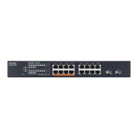
The following figures show the front panels of the Switch.
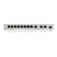
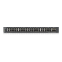
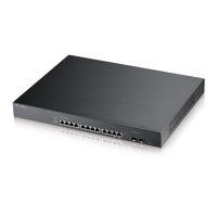
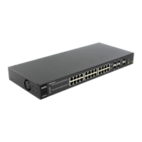
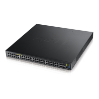
Figure 10 Front Panel: XMG1915-10E
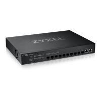
Figure 11 Front Panel: XMG1915-10EP
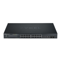
Figure 12 Front Panel: XMG1915-18EP
The following table describes the ports.
Table 6 Panel Connections
CONNECTOR /
BUTTON
DESCRIPTION
100M/1G/2.5G RJ-
45 Ethernet Ports
Port 1 – 8 (XMG1915-
10E / XMG1915-
10EP)
Port 1 – 16
(XMG1915-18EP)
These are 100M/1000M/2.5GBase-T auto-negotiating and auto-crossover Ethernet ports.
Connect these ports to a computer, a hub, a router, or an Ethernet switch.
100M/1G/2.5G RJ-
45 PoE Ports
Port 1 – 8 (XMG1915-
10EP / XMG1915-
18EP)
These are 100M/1000M/2.5GBase-T auto-negotiating and auto-crossover IEEE802.3bt PoE++
60 W ports.
A PoE port is an Ethernet port that can supply power to a connected device. Connect these
ports to a PoE-enabled IP camera / IP phone / AP, or an Ethernet switch.
 Loading...