64 CHAPTER 8: SETTING UP VIRTUAL LANS
To carry multiple VLANs across a single physical (backbone) link, each
packet must be tagged with a VLAN identifier so that the Switches can
identify which packets belong in which VLANs. To communicate between
VLANs a router must be used.
VLAN
Configuration
Examples
This section contains examples of VLAN configurations. It describes how
to set up your Switch to support simple untagged and tagged
connections.
Using Untagged
Connections
The simplest VLAN operates in a small network using a single switch. In
this network there is no requirement to pass traffic for multiple VLANs
across a link. All traffic is handled by the single Switch and therefore
untagged connections can be used.
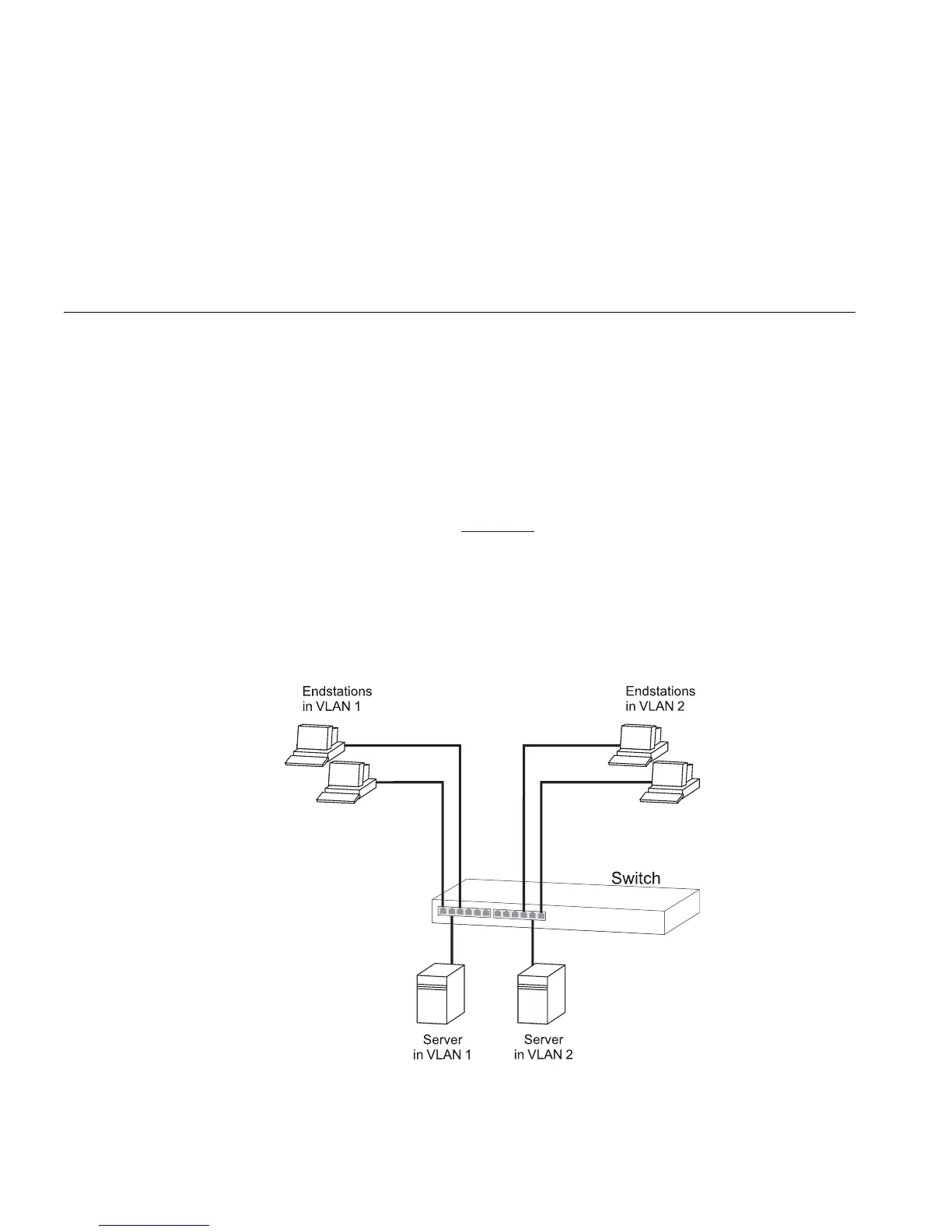
The example shown in Figure 17
illustrates a single Switch connected to
endstations and servers using untagged connections. Ports 1, 2 and 3 of
the Switch belong to VLAN 1, ports 10, 11 and 12 belong to VLAN 2.
VLANs 1 and 2 are completely separate and cannot communicate with
each other. This provides additional security for your network.
Figure 17 VLAN configuration example: Using untagged connections