38 CHAPTER 4: USING RESILIENCE FEATURES
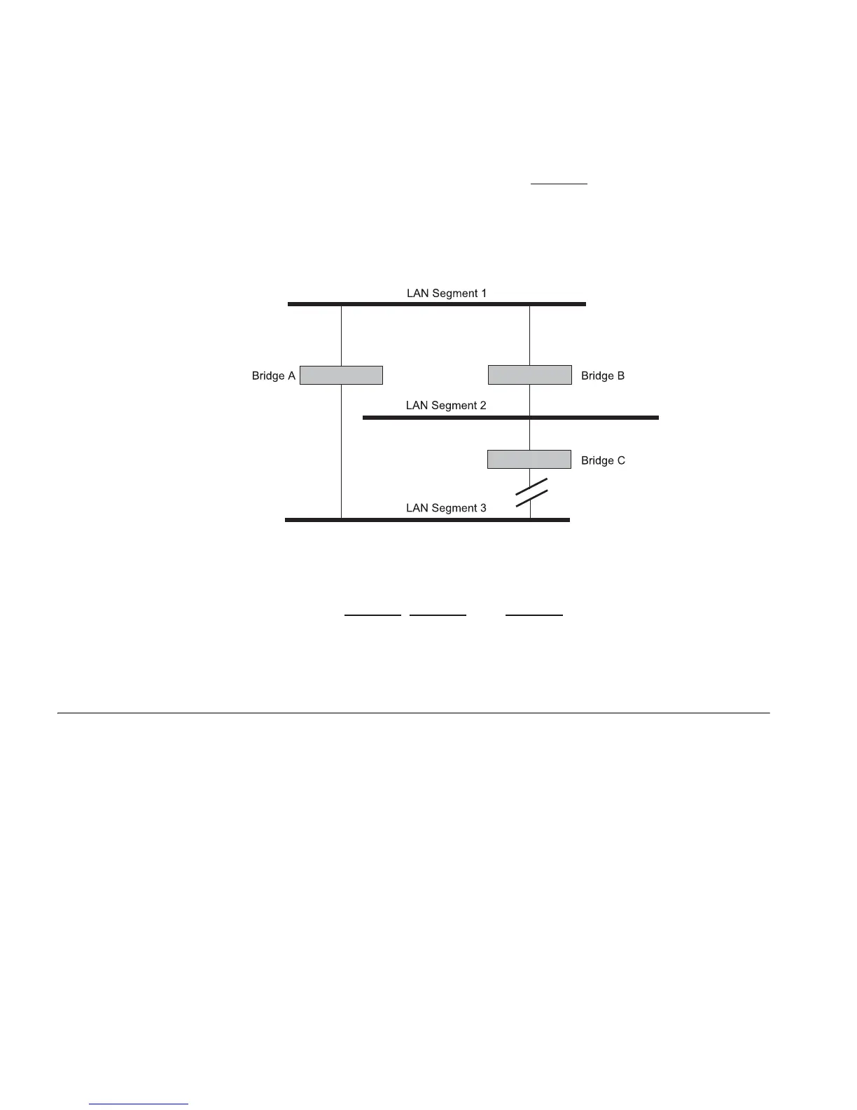
If a link failure is detected, as shown in Figure 7, the STP process
reconfigures the network so that traffic from LAN segment 2 flows
through Bridge B.
Figure 7 Traffic flowing through Bridge B
STP determines which is the most efficient path between each bridged
segment and a specifically assigned reference point on the network. Once
the most efficient path has been determined, all other paths are blocked.
Therefore, in Figure 5
, Figure 6, and Figure 7, STP initially determined that
the path through Bridge C was the most efficient, and so blocked the
path through Bridge B. After the failure of Bridge C, STP re-evaluated the
situation and opened the path through Bridge B.
How STP Works When enabled, STP determines the most appropriate path for traffic
through a network. It does this as outlined in the sections below.
STP Requirements Before it can configure the network, the STP system requires:
■ Communication between all the bridges. This communication is
carried out using Bridge Protocol Data Units (BPDUs), which are
transmitted in packets with a known multicast address.
■ Each bridge to have a Bridge Identifier. This specifies which bridge acts
as the central reference point, or Root Bridge, for the STP system —
the lower the Bridge Identifier, the more likely the bridge is to become
the Root Bridge. The Bridge Identifier is calculated using the MAC
address of the bridge and a priority defined for the bridge. The default
priority of your Switch is 32768.