VLAN Configuration Examples 65
To set up the configuration shown in Figure 17:
1 Configure the VLANs
Define VLAN 2 on the Switch. VLAN 1 is the default VLAN and already
exists.
2 Add ports to the VLANs
Add ports 10, 11 and 12 of the Switch as untagged members to VLAN 2.
You can use the Switch Web Interface to change VLAN configuration.
VLAN configuration can be found at Bridge > VLAN.
Using 802.1Q Tagged
Connections
In a network where the VLANs are distributed amongst more than one
Switch, you must use 802.1Q tagged connections so that all VLAN traffic
can be passed along the links between the Switches. 802.1Q tagging can
only be used if the devices at both ends of a link support IEEE 802.1Q.
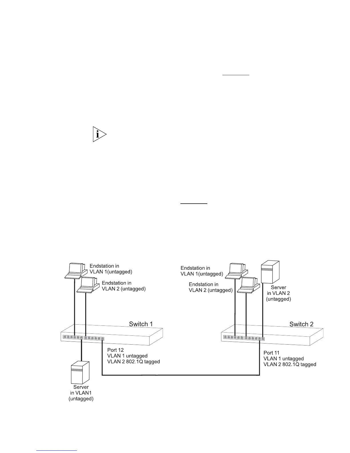
The example shown in Figure 18
illustrates two Switch units. Each Switch
has endstations and a server in VLAN 1 and VLAN 2. All endstations in
VLAN 1 need to be able to connect to the server in VLAN1 which is
attached to Switch 1 and all endstations in VLAN 2 need to connect to
the server in VLAN2 which is attached to Switch 2.
Figure 18 VLAN configuration example: 802.1Q tagged connections