123D Systems, Inc.
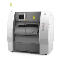
17. Disconnect cable X1 (B) from junction P-Jet of the affected extruder
PCB.
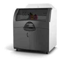
18. Using a 2.5 mm hex head driver, loosen and remove the four 2.5 mm
hex head bolts securing the delivery tube bracket to the extruders.
NOTE: For printers with only 1 extruder, the 2 right side
bolts will need to be removed. For printers with 2 extruders,
the 2 right side bolts and the center bolt will need to be
removed. For both of these congurations, the left bolt will
not be used.
NOTE: For clarity, the main extruder PCB was removed
from the illustration. It does not need to be removed for this
procedure.
19. Gently pull upward on the delivery tube bracket. As it separates from
above the extruders, cut the print material just below the end of the
delivery tube using the included wire cutters. Leave three inches of
material exposed from the top of the extruder.
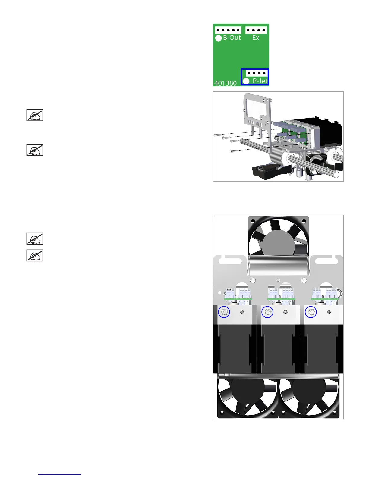
20. Using a 2.5 mm hex head driver, loosen the 2.5 mm hex head screw
from the affected extruder.
NOTE: The screw will remain loose in the extruder housing.
NOTE: For clarity, the main extruder PCB was removed
from the illustration. It does not need to be removed for this
procedure.
Right Rear View