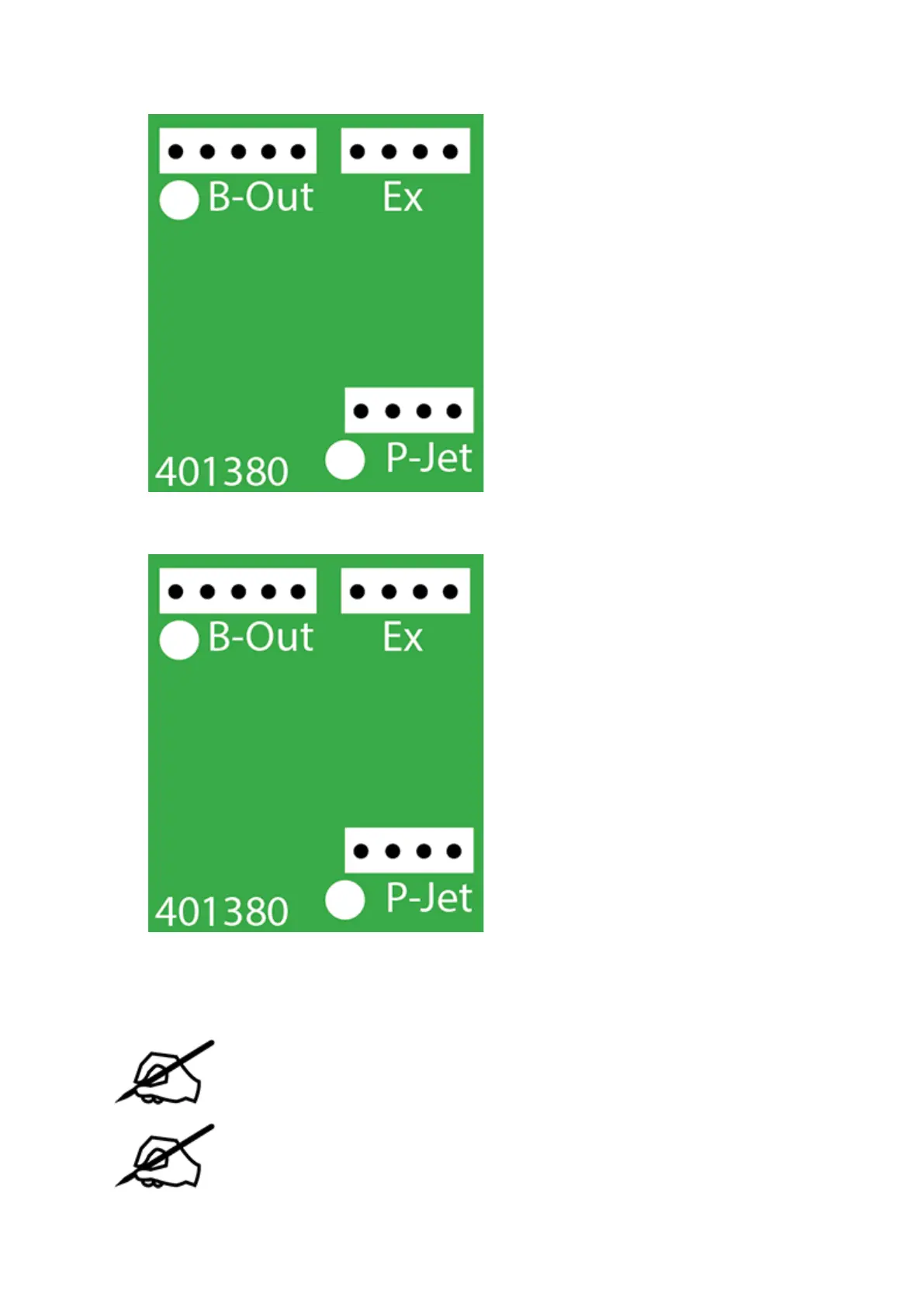
Disconnect the 5-pin jumper cable from junction B-Out of the extruder 2 PCB.16.
Disconnect cable X (B) from junction Ex of the extruder 2 PCB.17.
Using a 2.5 mm hex head driver, loosen and remove the four 2.5 mm hex head bolts18.
securing the delivery tube bracket and block to the extruders.
NOTE: For printers with 2 extruders, the 2 right side bolts and the center bolt
will need to be removed. For printers with 3 extruders, the left bolt will also
need to be removed.
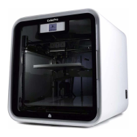
NOTE: For clarity, the main extruder PCB was removed from the illustration.
However, it does not need to be removed for this procedure.
 Loading...