AMT/PTD/PBX/0020/2/4/EN 01/2007 Page 121
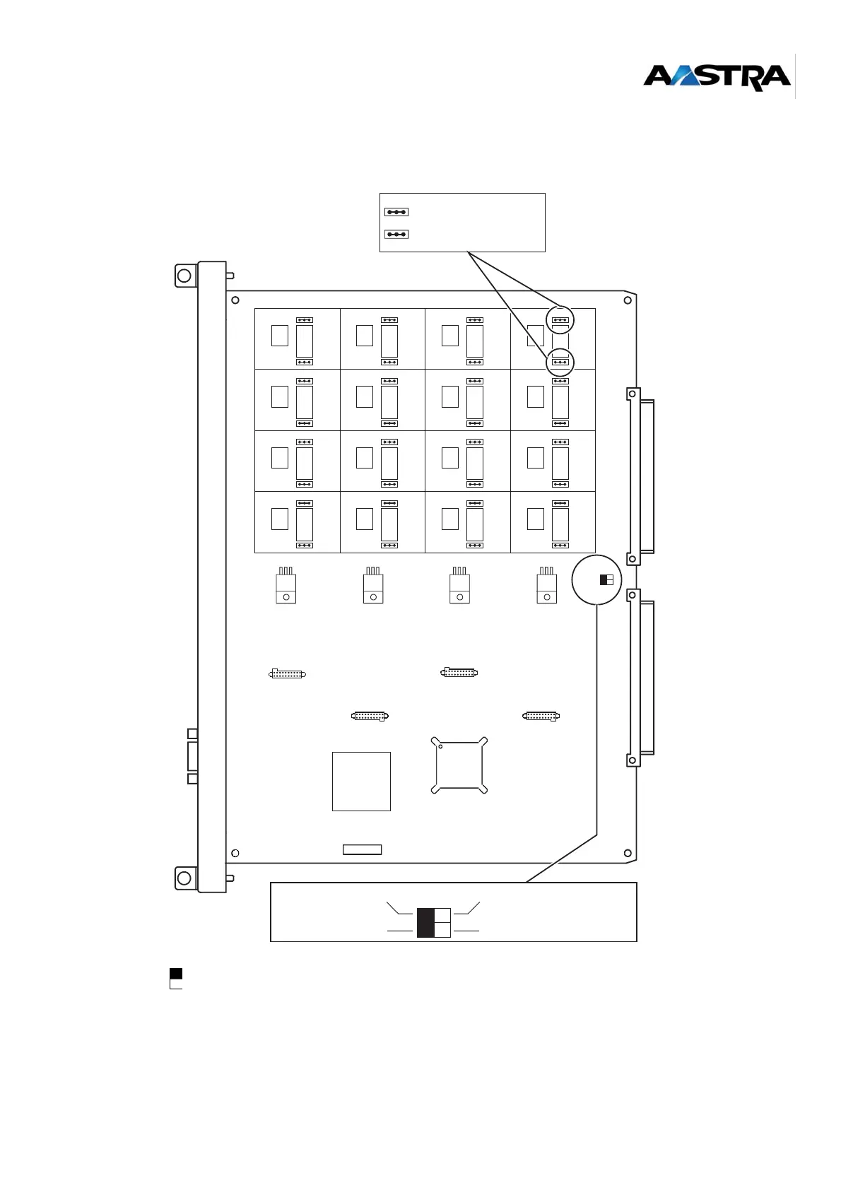
6.2.3 Equipment on top side
The black square represents the position of the switch.
J7, J8: ADPCM32B daughter card equipment
J11, J12: equipment of second ADPCM32B daughter card
Figure 6-2: Top view of the LDT card
J2
0
123
J1J2
4
123
J1J2
8
123
J1J2
12
123
J1
J2
1
123
J1J2
5
123
J1J2
9
123
J1J2
13
123
J1
J2
2
123
J1J2
6
123
J1J2
10
123
J1J2
14
123
J1
J2
3
123
J1J2
7
123
J1J2
11
123
J1J2
15
123
J1
J4
J12
J1J1
J11
J8
J7
CA1_1
123
J2 (+ 48 V or + 40 V)
J1 (- 48 V or - 40 V)
CA1
Master
Slave
Automatic
resynchronisation
resynchronisation
LDS operation without
 Loading...