AMT/PTD/PBX/0020/2/4/EN 01/2007 Page 97
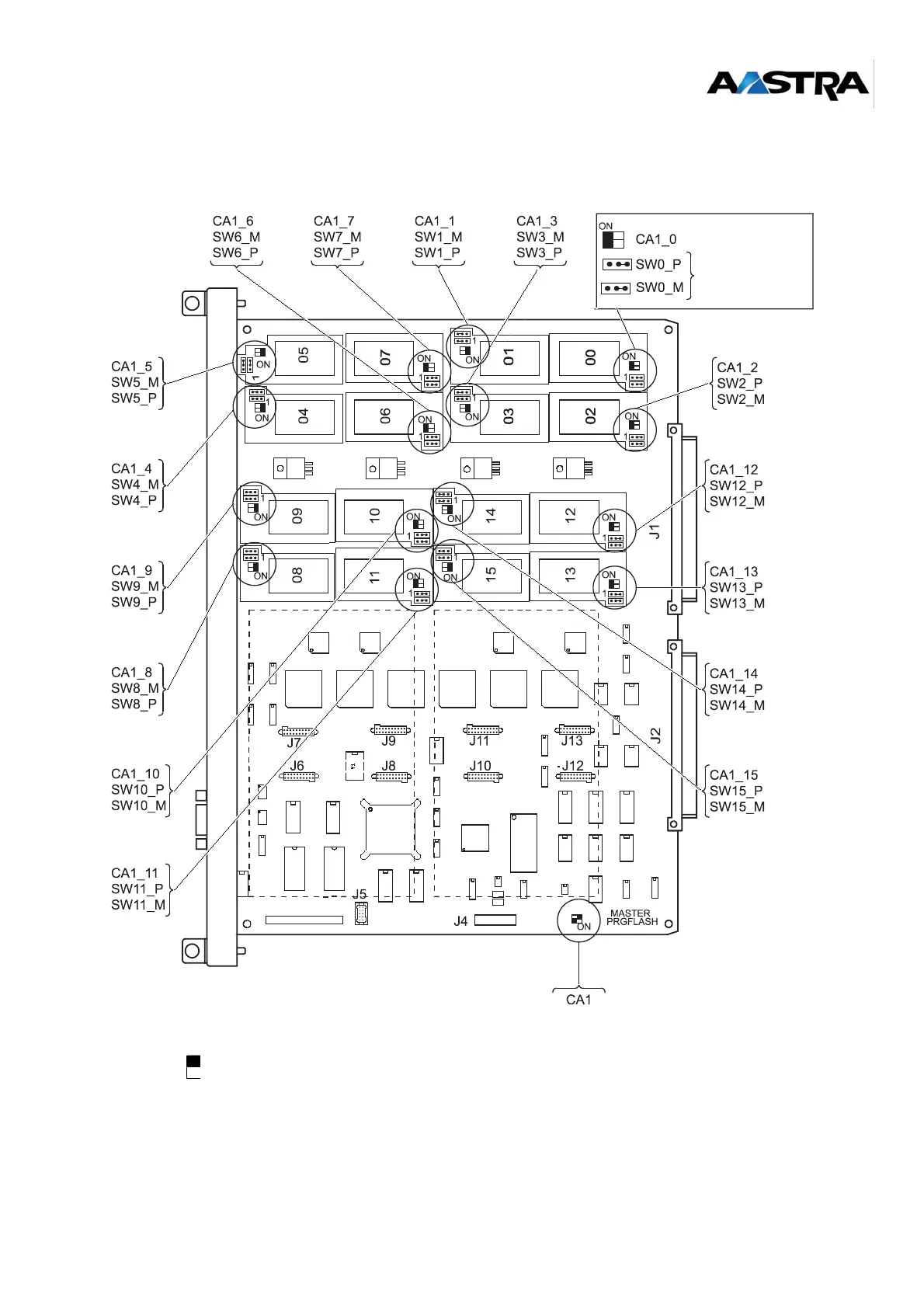
5.2.3 Equipment on top side
The black square represents the position of the switch.
J6, J7, J8, J9: ADPCM32 daughter card equipment
J10, J11, J12, J13: equipment of second ADPCM32 daughter card
Figure 5-2: Top view of the LDS card
C
0
(0
,1
)
C
6
(1
2
,1
3
)
C
2
(4
,5
)
C
4
(8
,9
)
C
5
(1
0
,11
)
C
3
(6
,7
)
C
1
(2
,3
)
C
7
(1
4
,1
5
)
1
-2
O
N
2
-3
O
F
F
ADPCM32
ADPCM32
power supply
1 2 3
power supply