AMT/PTD/PBX/0020/2/4/EN 01/2007 Page 71
4.3.1 Description of the connectors
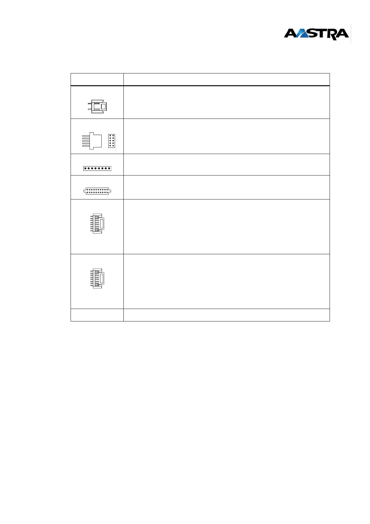
Table 1: Description of the LD4 ST card connectors
Label Feature
J2 40 V remote power supply connection
J3 Factory reserved.
J4 Factory reserved
J5 and J6 ADPCM 16 daughter card connection
J7 Connection for 2 DECT base stations
Interface 2:
Pin 5: ED2
Pin 6: NED2
Pin 7: RD2
Pin 8: NRD2
Interface 3:
Pin 1: ED3
Pin 2: NED3
Pin 3: RD3
Pin 4: NRD3
J8 Connection for 2 DECT base stations
Interface 0:
Pin 5: ED0
Pin 6: NED0
Pin 7: RD0
Pin 8: NRD0
Interface 1:
Pin 1: ED1
Pin 2: NED1
Pin 3: RD1
Pin 4: NRD1
J9 Not fitted
1
2
A B
A B
1
2
3
5
4
1
2
3
5
4
1
8
1
8