Page 136 01/2007 AMT/PTD/PBX/0020/2/4/EN
7.2 Distributing DECT synchronization to the base stations
7.2.1 Distribution by M bit
Here the synchronization signal is distributed to the base stations by the M bit of the S0 frame
from the DECT interface card (LD4/LD4N cards for the M6501 L/R/RM IP PBX (F1), LD4/LD4NX
cards (LD4N or LD4X mode) for the NeXspan S/L/D (F6), LDS card for the M6540 IP PBX (F2) ,
LDT card for NeXspan 50 (F4) equipped with FPHBG2/CSI and the LDT card for NeXspan 500
(F4) equipped with FPS/CSI.
In an F2 or F4 (equipped with FPHBG or FPS, CSH or CSI, LDS and/or LDT), a master LDS card
(or LDT card in an F4) synchronizes the slave LDS card (and/or LDT card in an F4) through
wiring on the distribution frame. In this mode, multisite handover in an F2 and/or F4 network is
possible provided that bit synchronization (2.048 Mhz clock) is carried out (by inter-site link).
7.2.2 Distribution by 3rd pair
The base stations of the different sites must be synchronized by wiring a third pair in the
following circumstances:
• if the installation has several PBXs not equipped with DECT synchronization ports
• configuration using integrated S0 accesses of the first generation NeXspan S CPU card
(UCT1-S).
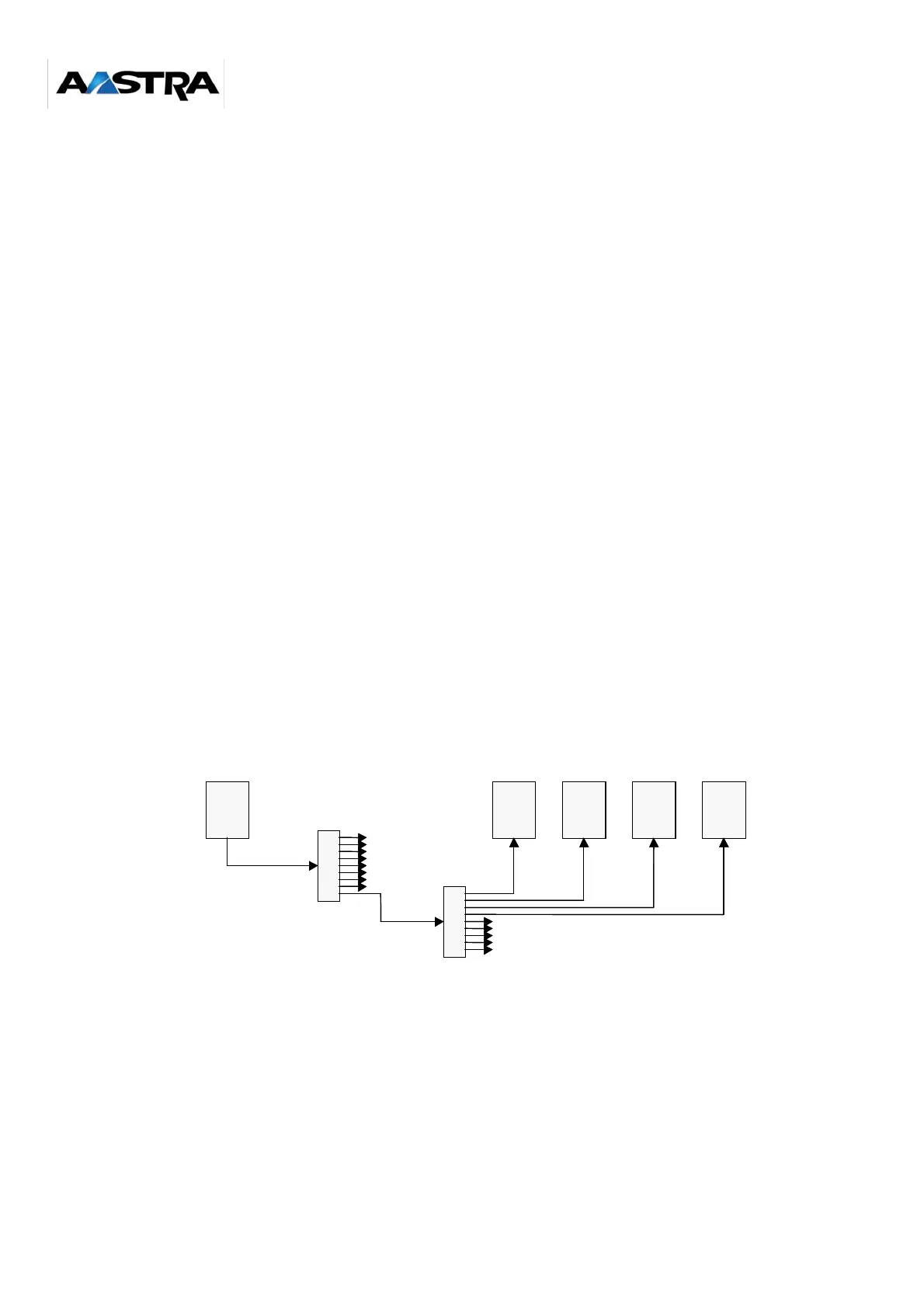
In this case, the synchronization signal is distributed by a 3rd pair from a master base station to
the slave base stations. Between one and four slave base stations may be connected to the
master base station. If there are more than 5 base stations, a repeater is required to distribute
the clock synchronization generated by the master base station.
Figure 7-1: Distribution by 3rd pair
third pair
Master base station Slave base stationsRepeaters