AMT/PTD/PBX/0020/2/4/EN 01/2007 Page 25
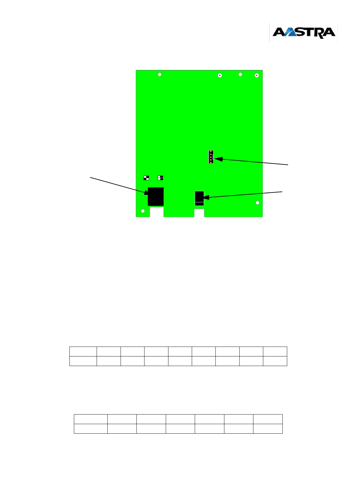
• J202: power supply jack used to supply power locally to the base station.
The black square represents the position of the switch.
Figure 2-3: Overview of the electronic card on the old M6241 base station
New M6241 base station connections
The base station is connected to its environment using 5 connectors:
• J1: HE14 connector - 5 pins, used for a debug console (reserved for the factory)
• J2: RJ45 female connector for connection to the PBX:
-4
pins are used for connection to the S0 Basic Rate Interface (pins 3 to 6)
-
2 pins are used for connection to the synchronization signal (pins 1 and 2), for
synchronization by 3rd pair
Note: The RSx pair carries the S0 BRI receive signals from the PBX.
The ESx pair carries the S0 BRI transmit signals to the PBX.
• J3: 6-pin male STOCKO connector (J3) parallel wired on the 6 useful pins of the RJ45
connector. It is used for CAT5 cable wiring.
• J4: HE14 connector - 8 pins, used for the JTAG port (reserved for factory)
Pin 1 2 3 4 5 6 7 8
Signal SYNC+ SYNC- ESa RSa RSb ESb - -
Pin 1 2 3 4 5 6
Signal SYNC+ SYNC- ESa RSa RSb ESb
CA1
1
2
ON 1
2
ON
S202
*
6
5
0
0
_
D
E
C
T
_
C
A
R
T
E
_
O
L
D
_
B
O
R
N
E
_
0
1
_
0
1
J1
J202
J201