2 System description
6 | 266 MODBUS® multivariable transmitter User manual 2105216 Rev. AB
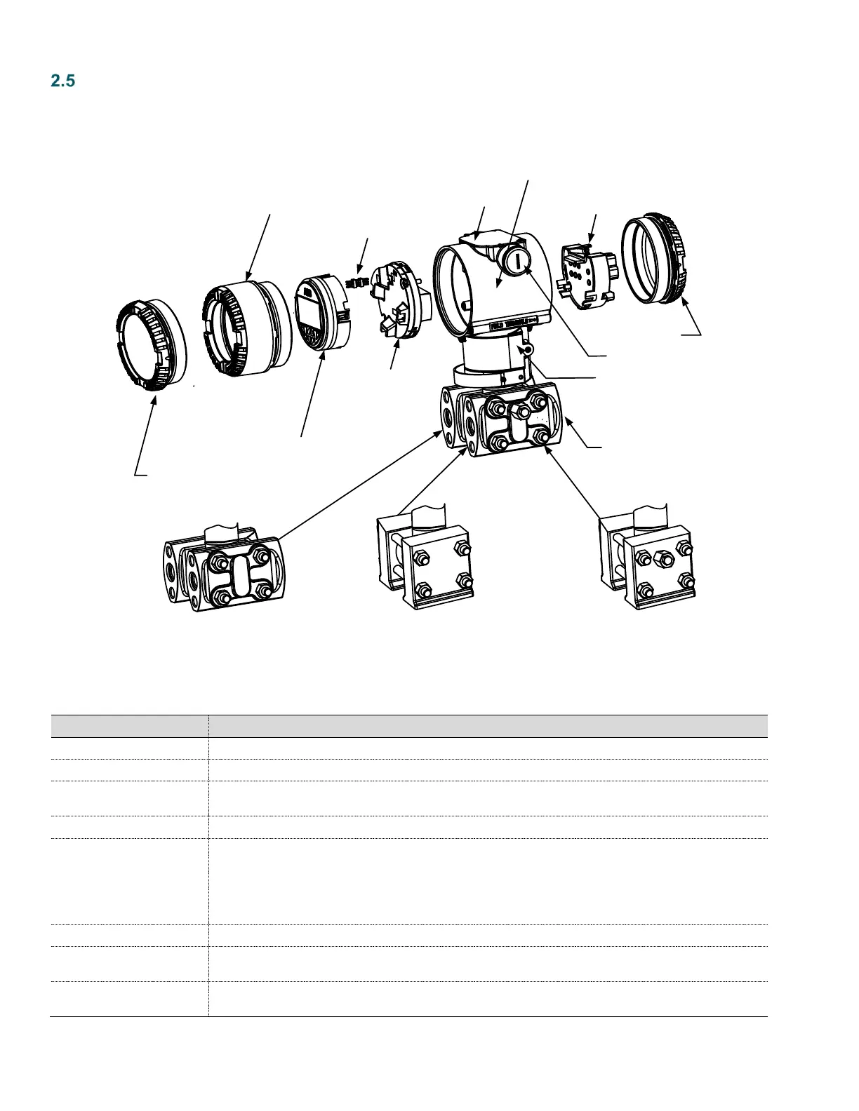
Transmitter hardware subassemblies
The 266 transmitter consists of multiple subassemblies (Figure 4). Table 1 explains each subassembly and provides additional
information.
Horizontal flange
with drain
Type 2-2 Blindcover
Type 2-2 Blindcover
Type 2-2 Windowcover
Meter LCD (HMI)
HMI 6-pin connector
MODBUS
®
Electronics
module
Nameplate
MODBUS
®
Terminal
block + surge protection
Housing, sensor, and flange
(see flange options)
Vertical flange
with drain
Vertical flange
without drain
Horizontal flange
without drain
Certification plate
½ inch NPT
Figure 4: 266 MODBUS
®
multivariable transmitter exploded view
Table 1: Transmitter subassemblies
Provides optional certification information, if purchased
Provides access to the wiring terminations
Provides visual access to the LCD display. Removal of the window cover provides access to the user
interface and the hardware DIP switch settings.
Provides connection between the meter LCD assembly and electronics module
Housing, sensor, and flange
The housing protects the transmitter components from environmental conditions and also provides an
explosion-proof rating for the unit. The housing includes two NPT entry points for field wiring and a nameplate
which states the product ID and the unit serial number. The sensor assembly, which provides the electrical
signal from the transducer to the electronics module, is located in the housing neck. The flange assembly
provides the connection to the process stream and is factory-installed in the lower housing neck. The
housing, sensor, and flange assembly are not field repairable or replaceable.
Provides viewing of parameters and readings
MODBUS
®
electronics
module
Main electronics board, which provides communication and display interface. The electronics module also
contains the DIP switches, which are used to write-protect the device and restore configuration data.
MODBUS
®
terminal block +
surge protection
The terminal block provides field wiring terminations for power, RTD, and RS-485 communications. This
assembly also provides surge protection for the remaining electronics.