6 Troubleshooting
74 | 266 MODBUS® multivariable transmitter User manual 2105216 Rev. AB
Verifying power connections
A low power or no power connection to the transmitter may be the cause of a blank LCD screen.
WARNING – Bodily injury. When the housing covers are removed and power is still connected, there is a
potential for explosion. Failure to observe this safety information may result in death or severe injury.
Do not remove housing covers in hazardous (classified) areas or explosive environments unless the area is
known to be non-hazardous. Verify an explosive atmosphere is not present when before removing the housing
covers and the power is live.
This procedure requires the transmitter to remain powered up.
1. Using a multimeter, measure the power source and verify that it is transmitting at least 10.5 Vdc, but less than 30 Vdc.
a. If the voltage is outside of this range, determine the cause and repair.
b. If a correction was made to the power source and the LCD screen is now visible and operational, it is not necessary
to continue this procedure. Follow the instructions in section 5.2.2, Securing the housing cover, to secure the unit.
2. If the power transmission is within the proper range, and the screen is still blank, verify that the power supply at the
termination block is within range.
a. Leaving the transmitter powered-up, use the instructions in section 5.2.1 to remove the rear housing cover, exposing
the terminal block.
b. Using a multimeter, measure the power supply at the termination block and verify it is receiving at least 10.5 Vdc, but
less than 30 Vdc. If the voltage is outside of this range, determine the cause and repair.
c. If a correction was made and the LCD is now visible, go to step 5.
3. If the power supply at the termination block is within the proper range, and the screen is still blank, verify that the positive
and negative power supply wires are tightly connected to the proper terminals on the termination block.
a. Disconnect the power supply to the transmitter.
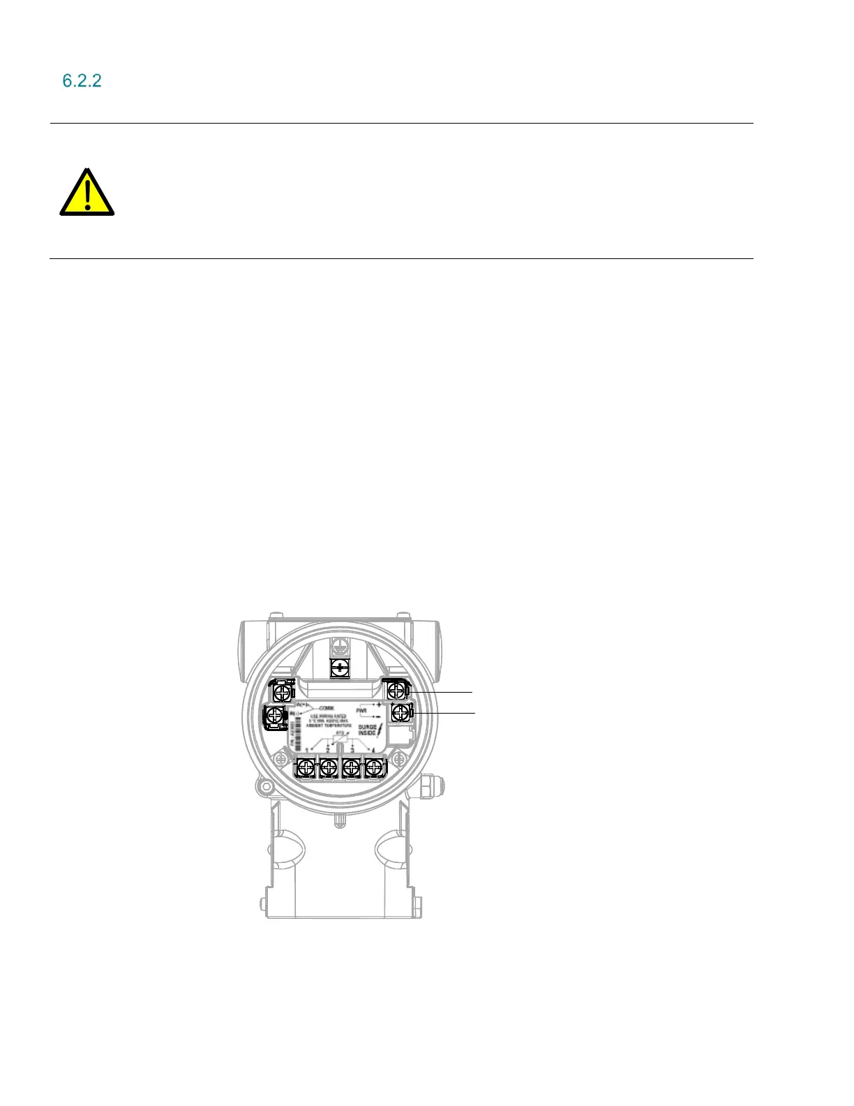
b. Compare the actual wiring to the termination identification printed on the block (Figure 51). Verify that the wiring is
correct, the terminal screws are tight, and the supply lines are firmly connected.
Figure 51: Transmitter power connections
i. If no corrections were necessary to the wiring on the terminal block, go to section 6.2.3, Verifying HMI connector
viability.
ii. If the wiring is incorrect (reversed polarity or loose terminal screws), make adjustments and then go to step 4.
Power Supply
10.5 to 30 Vdc
(+)
(-)