3 Installation
266 MODBUS® multivariable transmitter User manual 2105216 Rev. AB | 31
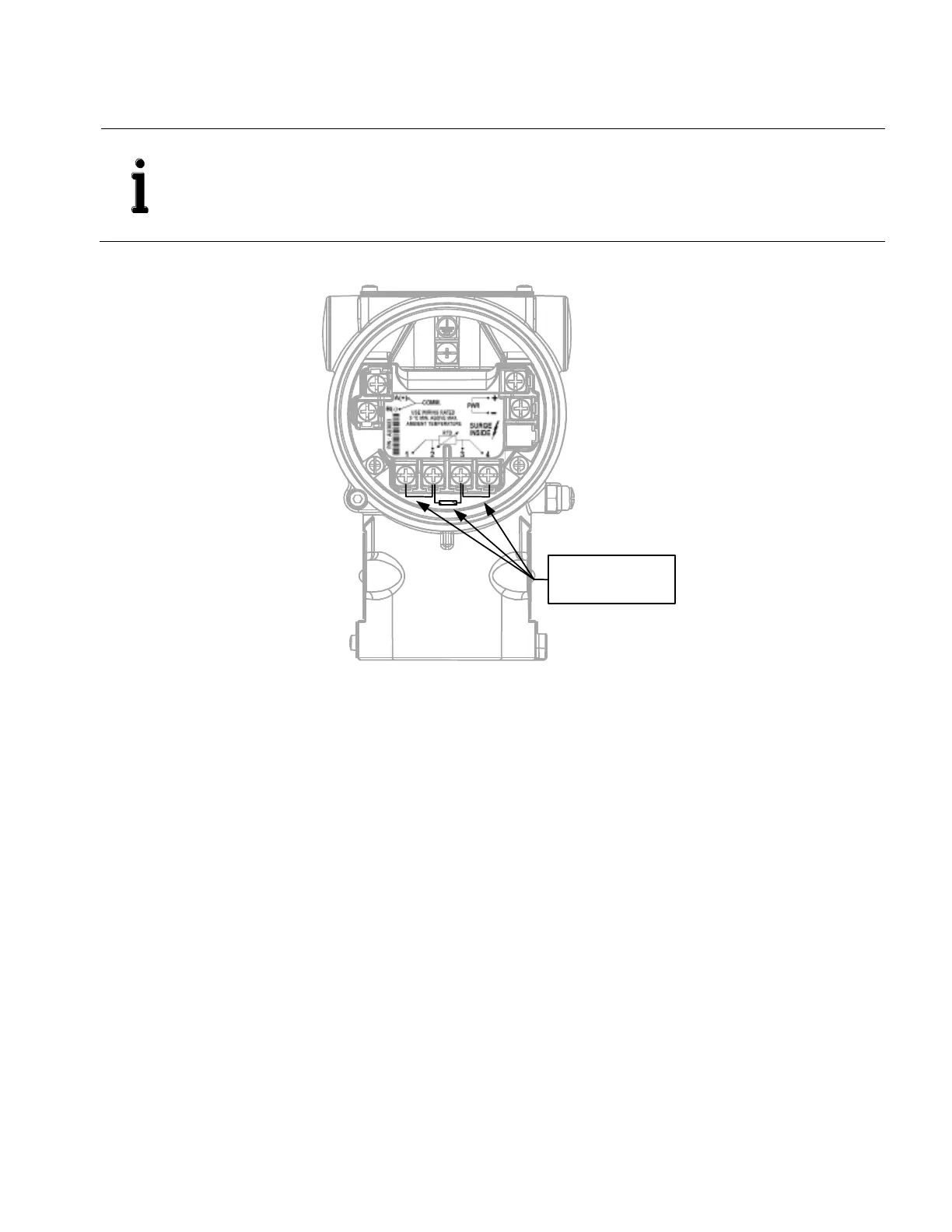
3. If a live temperature sensor (RTD) is installed in the meter run, remove the jumpers and resistor from the RTD terminals on
the termination block. Otherwise, continue to step 5.
a. Using a small phillips screwdriver, loosen the terminal 2 and 3 screws (Figure 26) and remove resistor.
RTD Simulation:
178 Ω resistor with
2 jumper wires
Figure 26: RTD Simulation wiring
b. Loosen the terminal 1 screw and remove the jumper wire.
c. Loosen the terminal 4 screw and remove the jumper wire.
IMPORTANT NOTE: For the purpose of temperature simulation, a 178 Ω resistor (206 °C / 402.8 °F) with 2
jumpers has been installed between the terminals for the temperature RTD connection. This resistor (including
the jumpers in the case of 4-wire connections) must be removed before connecting the RTD. If a temperature
RTD is not connected, the resistor must remain in place. If an RTD is installed, the 178 Ω resistor removed
from the RTD terminals may be used as an RS- 485 Bus termination.