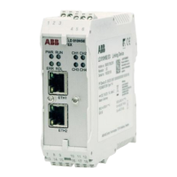
To maintain the operating temperature of the Linking Device, ensure that proper ventilation
is maintained in the enclosure:
• Depending on the installation position, different ambient operating temperatures are
allowed.
• Clearance between the Linking Device and the adjacent components or side walls
of the housing must be adhered to as illustrated in Figure 2.2.
Figure 2.2: LD 810HSE Ex Horizontal Installation Position
Provide a minimum space of 50 mm to the air inlet or air outlet.
Table 2.4: LD 810HSE Ex Maximum Ambient Operating Temperature for Horizontal
Installation
Maximum
permissible
ambient
temperature T
a
Minimum distance
Maximum fieldbus
voltage
Maximum number
of fieldbus
channels used
55 °C0 mm32 V DC4
60 °C0 mm24 V DC2
65 °C17.5 mm32 V DC4
70 °C17.5 mm24 V DC2
The maximum permissible ambient temperature values are also valid for a 180°
rotated installation position.
2PAA114135-610 30
2 Hardware Installation
2.4 Mounting and Dismounting

 Loading...