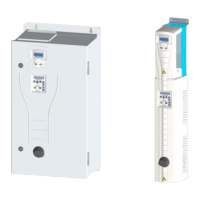
Do you have a question about the ABB ACH550 series and is the answer not in the manual?
| Enclosure | IP21, IP55 |
|---|---|
| Output Voltage | 0 to Supply Voltage |
| Frequency Range | 0 to 500 Hz |
| Control Method | Scalar control, vector control |
| Braking Chopper | Optional |
| Communication | Modbus RTU, Profibus, CANopen, Ethernet |
| Storage Temperature | -40°C to +70°C |
| Relative Humidity | 5 to 95 % RH, non-condensing |
| Altitude | Up to 1000 m (derating above 1000 m) |
| Cooling Method | Air-cooled |
Explains the types of safety instructions and warning symbols used in the manual.
Describes the manual as a supplement to the ACH550-UH User's Manual.
Lists the key features and functionalities of the E-Clipse Bypass.
Outlines the sequence of steps for installing the E-Clipse Bypass unit.
Details on drive identification and type code interpretation for installation.
Explains how to operate the HVAC bypass control panel for start-up.
Guides on modifying parameters using the start-up parameter list.
Details on altering parameters one by one from the full parameter list.
Describes the different modes accessible via the HVAC Bypass Control Panel.
Information on macro usage for parameter settings.
Detailed listing of bypass firmware parameters, their codes, and descriptions.
Covers the electrical installation of the EFB, including DIP switch and terminal connections.
Outlines the basic configuration steps for EFB when using the ACH550 drive.
Steps to establish communication between the bypass and a building management system.
Explains how the bypass reports error situations using LEDs and displays.
Recommended actions for addressing detected faults in the bypass system.
A table detailing fault codes, names, possible causes, and corrective actions.
A table listing alarms by code, name, description, possible causes, and actions.
Details on various bypass status conditions and their meanings.
Lists common error messages and their descriptions for parameter editing.
Information on branch circuit protection and fuses for input power.
Specifications for drive input fuses across different voltage ranges.
Information on optional input line reactors for added impedance.
Tables listing wire size capacities and torque for power terminals.
Mounting dimensions and weights for various enclosure types and frame sizes.
Lists standards that the E-Clipse Bypass configuration conforms to.