07 ELECTRICAL INSTALLATION
3BHS213401 E01 REV H ACS1000 AIR-COOLED USER MANUAL 98/184
7.6 Auxiliary power, control and serial
communication cables
7.6.1 Preparing the cable entry and the cables
7.6.1.1 Determining the cable length
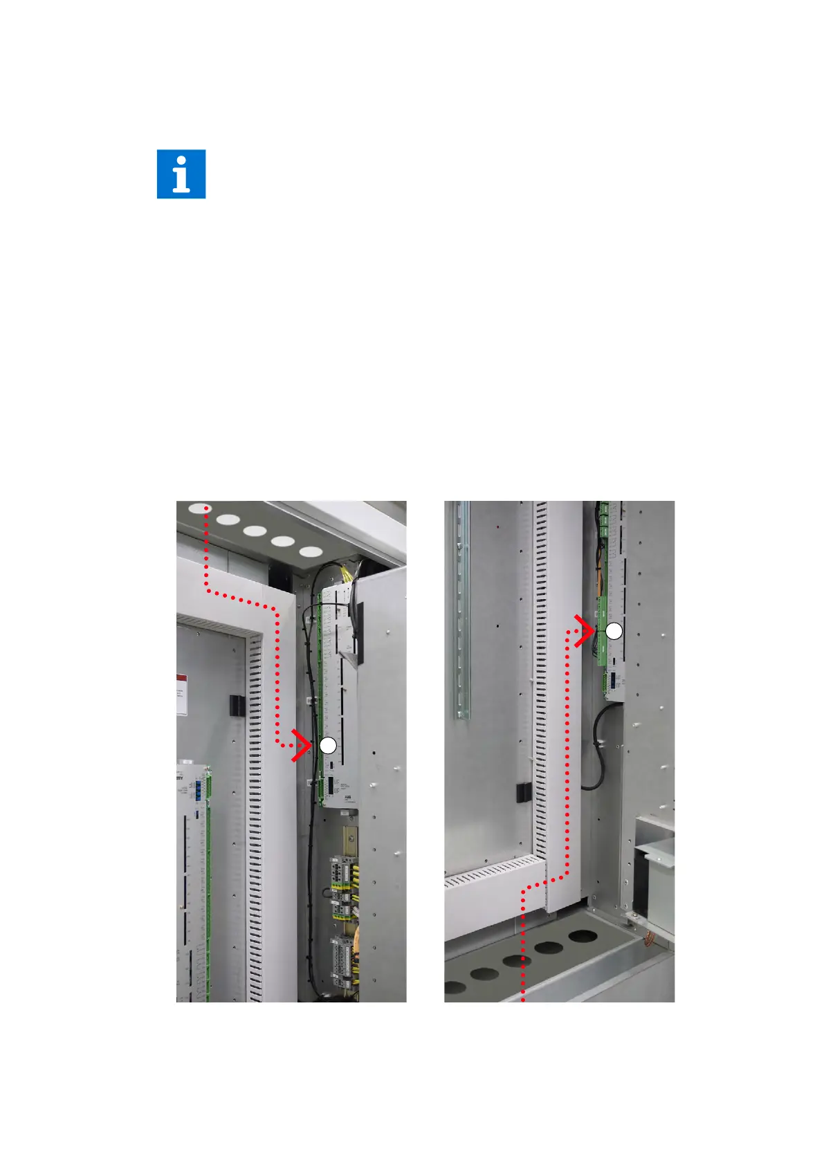
1. Determine the required length of a cable between the point of entry and the connection
point (1 in Fig. 7-12) inside the cabinet.
2. Cut the cable to the required length before connection.
Figure 7-12: Cable entry from top (A), from bottom (B)
See Layout drawing in Appendix C – Mechanical drawings for information on:
- Project-specific cable entry
- Dimensions between point of cable entry and terminals
See Appendix D – Wiring diagrams for information on:
- Conventions for cross-references and device identification
- Terminal designations
1
1
 Loading...


