07 ELECTRICAL INSTALLATION
3BHS213401 E01 REV H ACS1000 AIR-COOLED USER MANUAL 104/184
7.7 Power supply cable for redundant fan unit
This section applies to drives that are equipped with the optional
redundant fan.
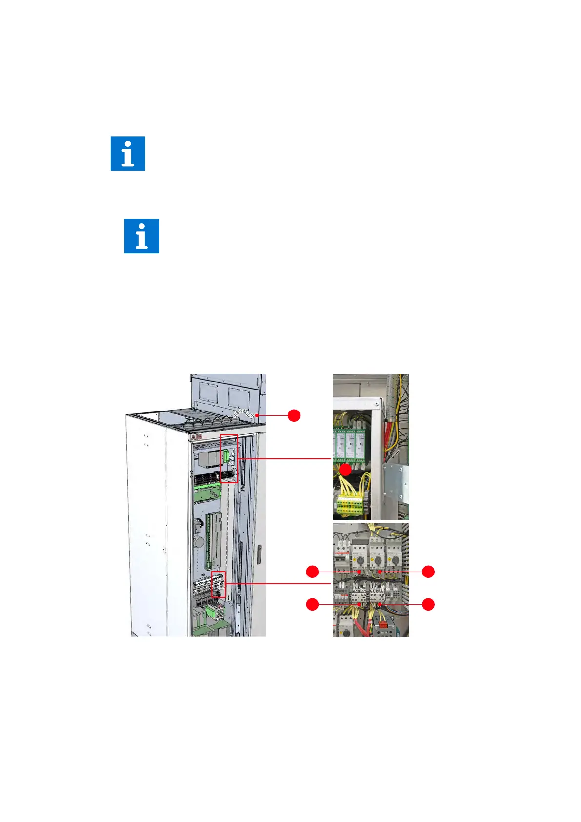
1. Enter the pre-fabricated multi-core cable into the cabinet as close as possible to the
redundant fan unit and according to the type of control cable entry used.
Note: The braided metal cable sleeve (1 in Fig. 7-18) does not have to be grounded at the
point of entry. If necessary, seal the gaps according to the type of cable entry used.
2. Route the wires to the terminals (2 and 3 in Fig. 7-18) as illustrated.
Note: Connection 3 in Fig. 7-18 depends on the type of fan, eg, AC or EC.
Figure 7-18: Routing, connecting the cable of the redundant fan unit
3. Connect the wires according to the terminal number on the marker sleeves.
For information on the cable connection, see “Appendix D – Wiring diagrams”.
For more information on cable entry, see:
- “7.6.1.2 Preparing cables for EMC plates” on page 99
- “7.6.1.3 Preparing cables for cable entries with sealing modules” on page 100
- “7.6.1.4 Preparing cables for cable entries with cable glands” on page 102
1
2
3
3
 Loading...


