11 PREVENTIVE AND CORRECTIVE MAINTENANCE
3BHS213401 E01 REV H ACS1000 AIR-COOLED USER MANUAL 160/184
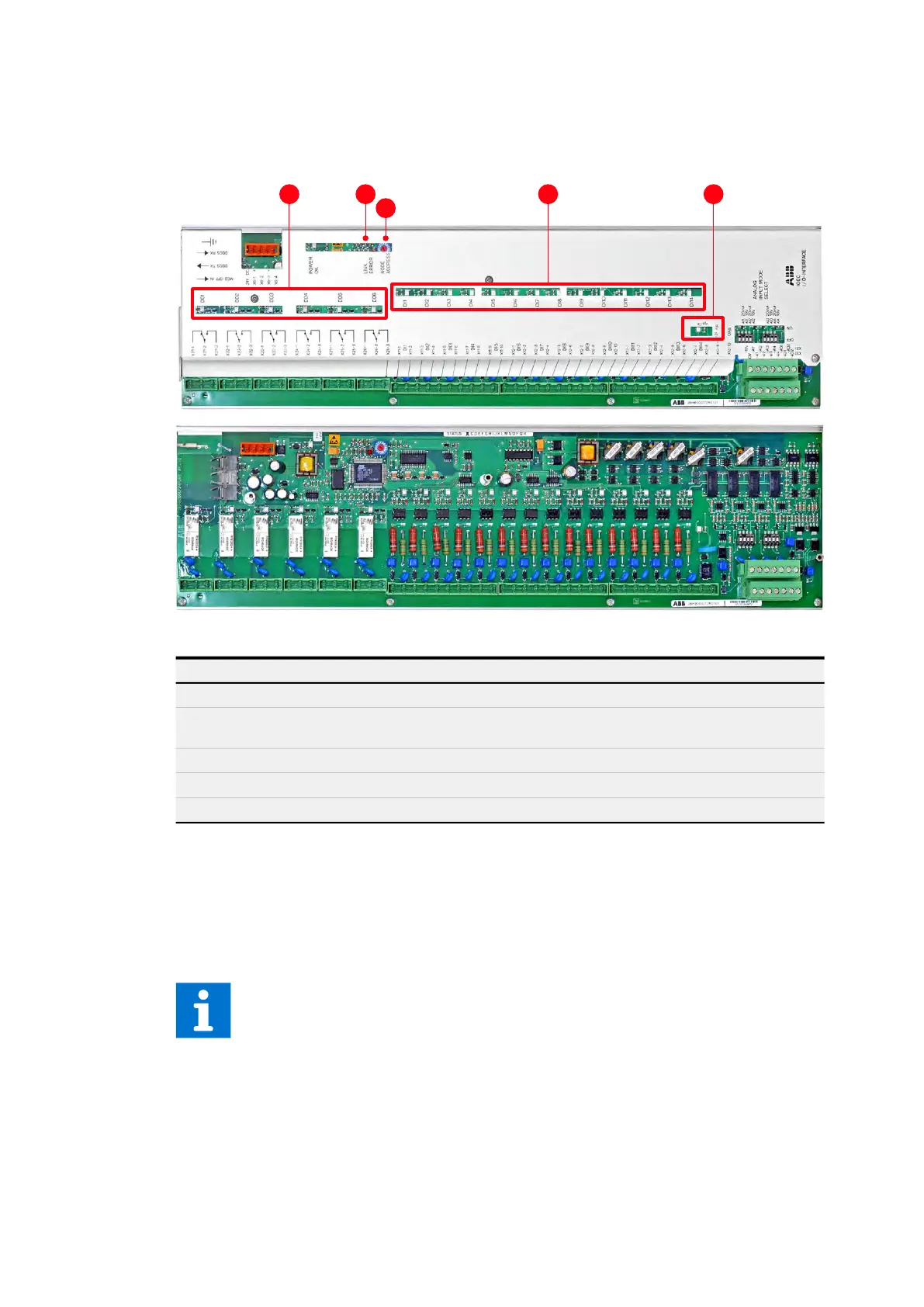
11.5.2 IOEC I/O modules
11.5.2.1 LEDs
Figure 11-3: IOEC module
11.5.2.2 Cluster address
Each IOEC module has a unique cluster address that identifies the module in the software and
links it to a parameter.
The address is set with the rotary switch on the module (3 in Fig. 11-3). The factory-set value
must not be changed.
LED Description
1 Status LEDs of digital outputs On when output is energized
2 Link error light Only on when there is a problem with the
optical fibers.
3 Rotary switch Sets the address
4 Status LEDs of digital inputs On when input is energized
5 Status LED of the 24 V internal voltage supply On when energized
1
2
3
4 5
For information on IOEC switch settings, see “Appendix C- Mechanical drawings”.
 Loading...


