07 ELECTRICAL INSTALLATION
3BHS213401 E01 REV H ACS1000 AIR-COOLED USER MANUAL 103/184
7.6.2 Connecting the cables
7.6.2.1 IOEC modules
- Connect the cables for digital and analog input and output signals to the
distribution terminals.
7.6.2.2 Conductors
- If a twisted pair cable is used, leave the unshielded cable ends twisted until they reach
the terminals.
- Leave unshielded conductor ends as short as possible (not longer than 50 mm).
7.6.2.3 Cable shields
- Connect the shield of serial communications cables to the fieldbus adapter.
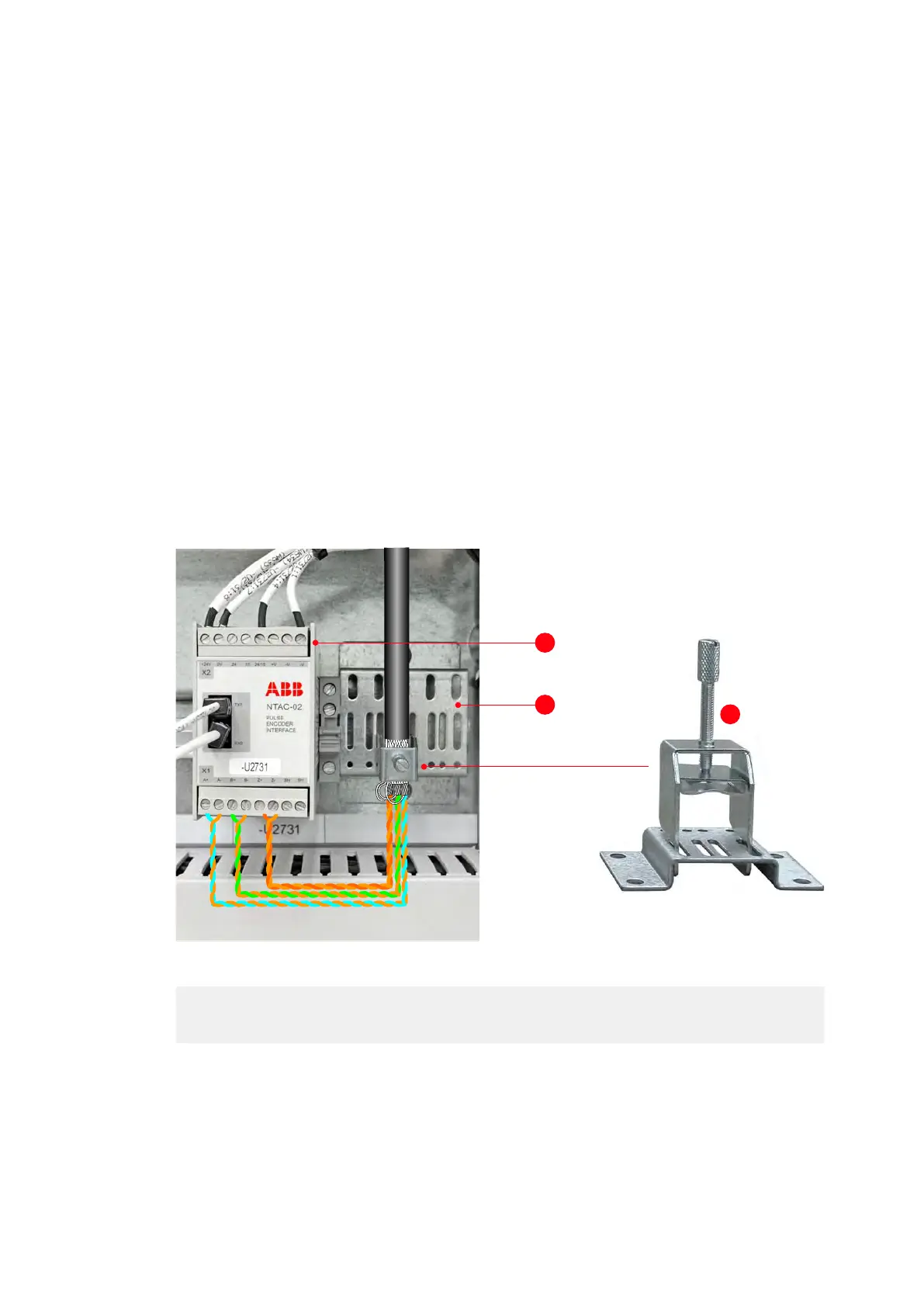
- Connect the overall shield and the individual shields of the encoder cable to the separate
shield grounding bracket (2 in Fig. 7-17). Do not connect the shields directly to the encoder
adapter (1 in Fig. 7-17).
Note: To accommodate encoder cables of different diameters, ground clamps (3 in Fig. 7-
17) of different sizes are supplied.
Figure 7-17: Shield grounding point for encoder cable
(1) Encoder adapter
(2) Shield ground bracket
(3) Grounding clamp
1
2
3
 Loading...


