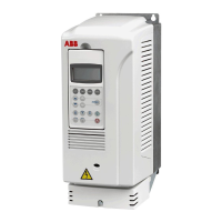
Drive module of frame size R7 with bottom exit
12
• EMC kit 64331116 containing two power cable lead-throughs with EMC sleeves
and rubber grommets, one control cable lead-through and gasket strip for EMC
shielding of the enclosure door. See also page 20.
Additional parts to be provided by the installer
The following parts, in addition to the Rittal and ACS800-04M parts listed above, are
needed in the installation:
• air baffle, see page 17.
• EMC screen, see page 16.
• 800 mm × 600 mm piece of wire mesh with max. 10 mm mesh size for fulfilling
IP20 degree of protection of the enclosure. The mesh is placed on the top of the
enclosure frame under the 50 mm spacers on which the enclosure roof lies. See
page 18.
• PE busbar of dimensions 70 mm × 50 mm × 10 mm, copper
• contactor (optional)
• auxiliary voltage transformer when a contactor is installed
• supply disconnecting device and input cable fuses. See ACS800-04/04M/U4
Hardware Manual [3AFE64671006 (English)], chapters Planning the electrical
installation and Technical data.
• terminal for grounding the control cable shields and self-adhesive strain reliefs to
be mounted next to the RDCU Drive Control Unit. See page 22
• shroud over the input cable terminal connections and output connections of the
disconnecting device.
Moving, unpacking and assembling the drive module
Follow the instructions given in ACS800-04/04M/U4 Cabinet Installation
[3AFE68360323 (English)]. Fasten the bottom exit kit (+H352) to the drive module
before beginning to install the drive module into the enclosure.
EMC power cable lead-
throughs
EMC control cable
lead-through
EMC gasket strip

 Loading...


