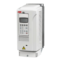
Drive module of frame size R7 with bottom exit
14
Installation steps
Step Instruction Photo
1 Fasten the base plates and lead-
through plates to the enclosure
frame. See also section Cable
lead-through plates on page 20.
2 Fasten the punched sections for
the side mounting plate fastening
to the vertical profiles of the
enclosure frame.
3 Fasten the devices to the side
mounting plate. See also section
Fastening of the RDCU Drive
Control Unit to the side mounting
plate on page 22.
4 Fasten the side mounting plate to
the punched sections.
5 Fasten the devices, and the drive
module if a lifting device is
available, to the back mounting
plate. See ARFI-10 EMC Filter
Installation Guide
[3AFE68317941 (English).
6 Connect the switch fuse to the
EMC filter, and the EMC filter to
the contactor with laminated
copper bars. Connect laminated
copper bars to the output of the
contactor.
7 Fasten the back mounting plate
to the enclosure frame 70 mm
from the back vertical profile. In
this location, the drive module will
face the enclosure door thus
allowing no hot air recirculation
into the drive module ventilation
grating from the inside of the
enclosure. See also Fastening of
the back mounting plate on page
21.
8 Fasten the drive module to the
back mounting plate if not
fastened already.
Side mounting plate
TS 8614.240
1100 mm × 300 mm
Punched section TS 8612.160
Punched section TS 8612.160
1025 (40.35)
C-rail 600 mm
Motor cable lead-throughs
Control cable lead-through
Input cable lead-throughs
Back mounting
plate (included in
the TS 8806.500
enclosure)
Base plates (included in the
TS 8806.500 enclosure)
820 (32.28)
1
3
4
1
1
1
2
BACK
2
FRONT
Left side view of the installation without side panel and EMC screen
5
5
5
5
6
6
7

 Loading...


