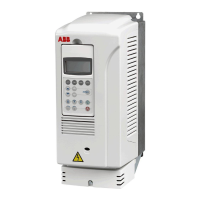
Drive module of frame size R8
34
Installation steps
Step Instruction Photo
1 Fasten the base plates and lead-
through plates to the enclosure
frame. See also section View of
base plates and cable lead-
throughs fastened on page 40.
2 Fasten the punched sections to
the back vertical profiles of the
enclosure frame. See also
section Fastening of the punched
sections on page 41.
3 Fasten the side mounting plate to
the enclosure frame.
4 Fasten the support rails onto
which the drive module will be
placed to the punched sections
of the enclosure frame. See
section Fastening the drive
pedestal to the enclosure frame
on page 41.
5 Fasten the vertical output
busbars to the drive pedestal.
6 Place the pedestal onto the
support rails and fasten the
pedestal to the enclosure frame.
See section Fastening the drive
pedestal to the enclosure frame
on page 41.
7 Fasten the contactor and
auxiliary voltage transformer to
the back mounting plate and
fasten the mounting plate to the
enclosure frame. See section
Fastening of the back mounting
plate on page 41.
8 Fasten the devices to the side
mounting plate.
9 Slide the drive module onto the
pedestal, connect the internal
busbars and fasten the module to
the pedestal as shown in
ACS800-04/04M/U4 Cabinet
Installation [3AFE68360323
(English)].
Back mounting plate
TS 8614.840
700mm×300mm
Switch fuse
Back fastening
bracket for the
vertical busbar
shroud
Punched section
TS 8612.180
1180 (46.46)
232 (9.13)
1553 (61.14)
PE terminal
Control cable lead-
throughs
Input cable lead-
throughs
1
3
1
1
2
Back view of the installation
7
5
6
PE busbar
Motor cable
lead-throughs
Base plates (included
in the TS 8806.500
enclosure)
1
2
2
8
10
10
11
4

 Loading...


