22 Installation
STO connections with safety relays
The following diagrams show examples of STO connections with safety relays for:
• single drives R2-R6 and R7-R8 (page 22)
• inverter modules R2i-R4i, R5i, R7i and R8i (pages 24-27)
• multiple drive/inverter modules or inverter units (page 28).
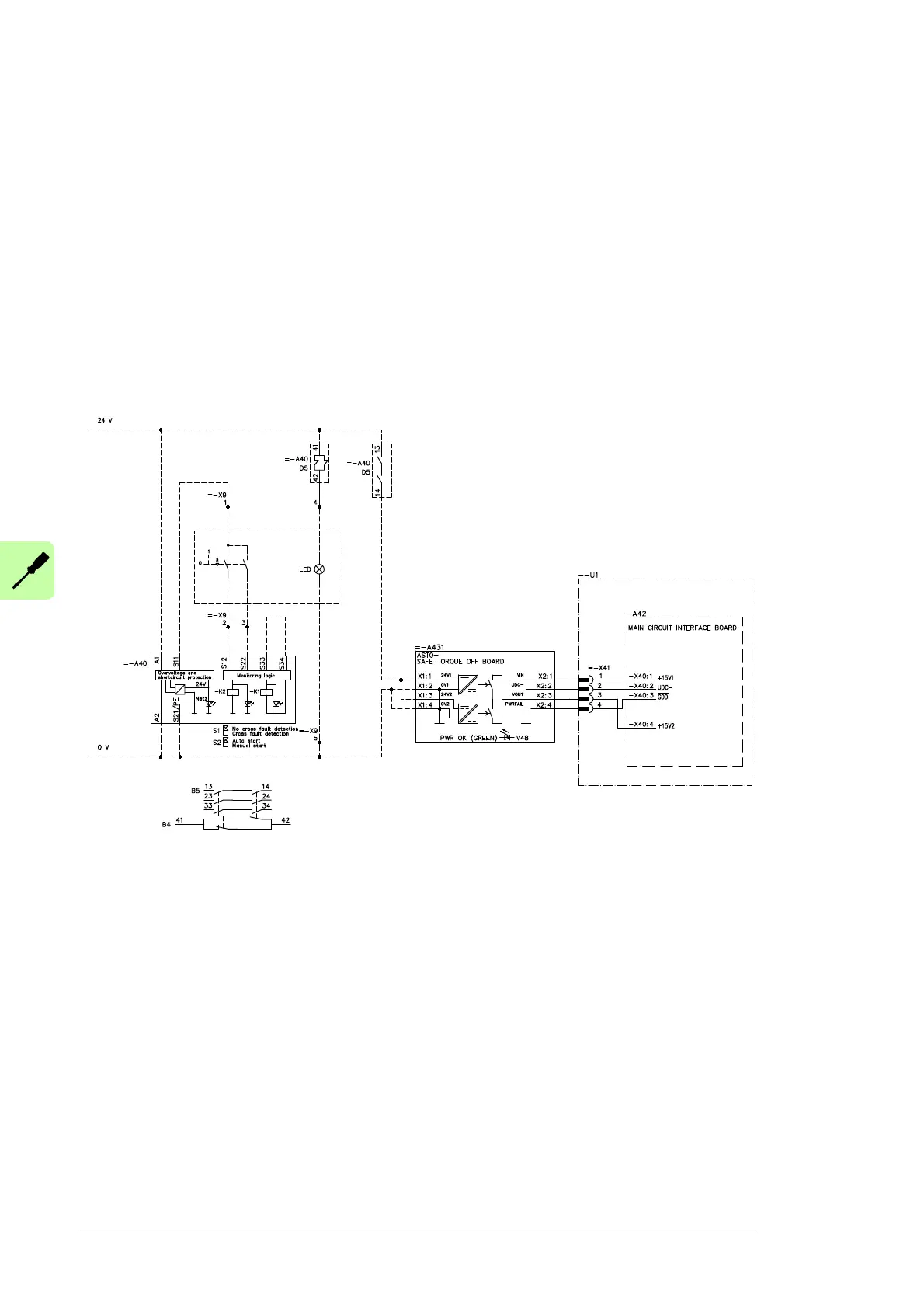
Note: The safety relay is not included in the delivery when the drive is equipped with
option +Q967. In the examples below, the recommended customer wiring of the safety
circuit (the activation switch, safety relay and ASTO board) are shown with a dashed line
(on the customer’s responsibility). The connection from ASTO board to drive/inverter is
shown with a solid line (included in STO kit deliveries).
Frame sizes R2 to R6
RINT-XXXX / GINT-XXXX
 Loading...


