Installing the sensor head 21
Establishing the connections
WARNING
Make sure to comply with the national electrical standards.
Disconnect power at the electrical distribution panel prior to performing any
adjustment (connections) on the sensor.
The sensor is equipped with four ports for cabling. Make sure the power cables (line
voltage) and all other cables are routed separately in a dedicated cable port through a
proper cable gland (i.e., there must never be more than one multi-strand cable through
any of the cable glands). Putting two cables through a cable gland invalidates the IP67
protection, allows water ingress and creates an electrical hazard.
Prior to establishing connections inside the CoreSense sensor:
1 Make sure to ground the CoreSense, either by means of the three-wire cable on the internal ground
wire of the power cable or with a separate cable to the external ground lug.
2 Install on the sensor the required watertight cabling.
—
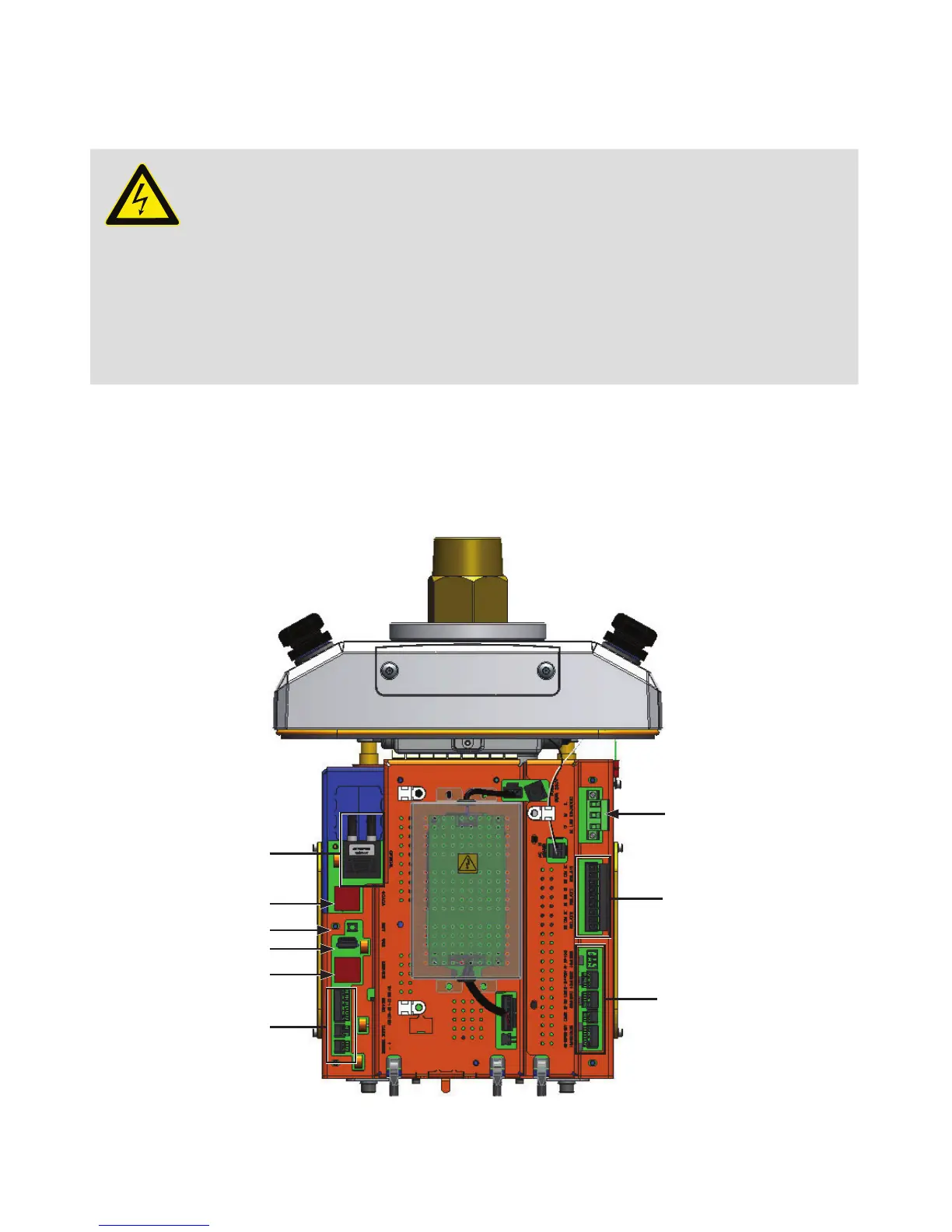
Figure 3 CoreSense port and relay connections
Optical Ethernet port
SCADA port
RESET button
USB port
Service Ethernet port
RS-485
AC Line 100–240 V AC
Relays
4–20 mA I/Os