DCS Type Line choke Fig.
400V-690V type
DCS60x-0025-41/51 ND01 1
DCS60x-0050-41/51 ND02 1
DCS60x-0050-61 ND03 1
DCS60x-0075-41/51 ND04 1
DCS60x-0100-51 ND06 1
DCS60x-0110-61 ND05 1
DCS60x-0140-41/51 ND06 1
DCS60x-0200-41/51 ND07 2
DCS60x-0250-41/51 ND07 2
DCS60x-0270-61 ND08 2
DCS60x-0350-41/51 ND09 2
DCS60x-0450-41/51 ND10 2
DCS60x-0450-61 ND11 2
DCS60x-0520-41/51 ND10 2
DCS60x-0700-41/51 ND12 2
DCS60x-0900-41/51/61/71 ND13 3
DCS60x-1200-41/51 ND14 3
DCS60x-1500-41/51/61/71 ND15 3
DCS60x-2000-41/51 ND16 3
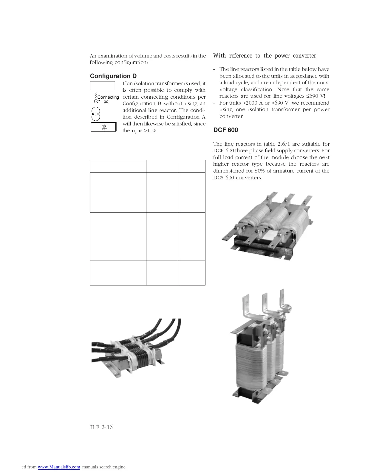
Line reactors L1
Fig. 1
Fig. 2
Fig. 3
Table 2.6/1: Line reactors (for more information see
publication
Technical Data)
An examination of volume and costs results in the
following configuration:
Configuration D
If an isolation transformer is used, it
is often possible to comply with
certain connecting conditions per
Configuration B without using an
additional line reactor. The condi-
tion described in Configuration A
will then likewise be satisfied, since
the u
k
is >1 %.
With reference to the power converter:
- The line reactors listed in the table below have
been allocated to the units in accordance with
a load cycle, and are independent of the units
voltage classification. Note that the same
reactors are used for line voltages
≤
690 V!
- For units >2000 A or >690 V, we recommend
using one isolation transformer per power
converter.
DCF 600
The line reactors in table 2.6/1 are suitable for
DCF600 three-phase field supply converters. For
full load current of the module choose the next
higher reactor type because the reactors are
dimensioned for 80% of armature current of the
DCS 600 converters.
Connecting
point
Line
II F 2-16