II F 2-24
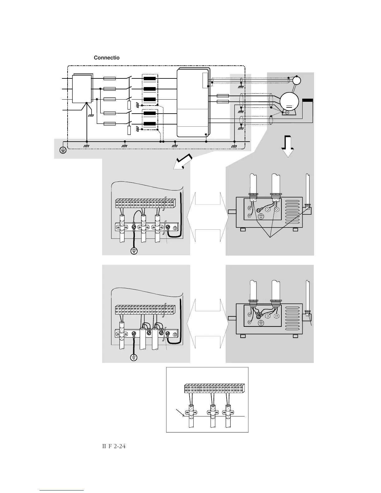
Connection example in accordance with EMC
Fig. 2.6/6: Connection example in accordance with EMC
Important hint:
The example shows the principle structure of
a DC drive and its connections. It is a not
binding recommendation, and it cannot re-
spect all conditions of a plant. Therefore
each drive must be considered separately
and with respect to the special application.
Additionally the general installation and safety
rules must be taken in account.
M
A1 A2
F1
F2
A1 A2
F1
F2
L1
L2
L3
PE
U1
V1
W1
C1
D1
1
7
5
3
PE
PE
PE
PE
A
F
AFTacho
AFTacho
T
I/O
Mounting plate
DC motor
Tacho
Screens
Contact to the motor
housing at the whole
screen perimeter
Filter
Mounting plate with PE
bar and terminals
PE bar
DC motor
Tacho
Screen
Mounting plate with PE
bar and terminals
PE bar
lower edge
of the PCB
carrier
Encoder inputs and
analogue I/O at the PCB
Field
supply
unit
Armature and field
cables with
screens for
"first environment"
Armature and field
cables without
screens suitable for
"second
environment"