II F 3-6
3.7 Software diagrams
Introduction
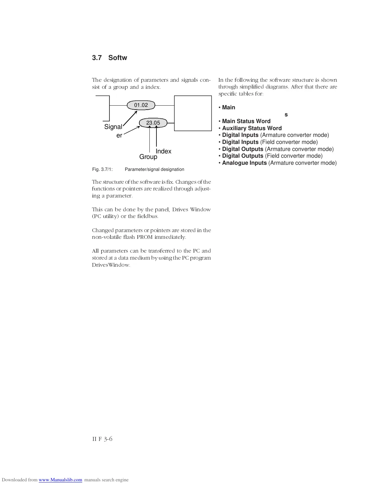
The designation of parameters and signals con-
sist of a group and a index.
X
Parameter
01.02
23.05
Signal
Group
Index
The structure of the software is fix. Changes of the
functions or pointers are realized through adjust-
ing a parameter.
This can be done by the panel, Drives Window
(PC utility) or the fieldbus.
Changed parameters or pointers are stored in the
non-volatile flash PROM immediately.
All parameters can be transferred to the PC and
stored at a data medium by using the PC program
DrivesWindow.
Fig. 3.7/1: Parameter/signal designation
In the following the software structure is shown
through simplified diagrams. After that there are
specific tables for:
• Main Control Word
• Auxiliary Control Words
• Main Status Word
• Auxiliary Status Word
• Digital Inputs (Armature converter mode)
• Digital Inputs (Field converter mode)
• Digital Outputs (Armature converter mode)
• Digital Outputs (Field converter mode)
• Analogue Inputs (Armature converter mode)