Control and Status
Words
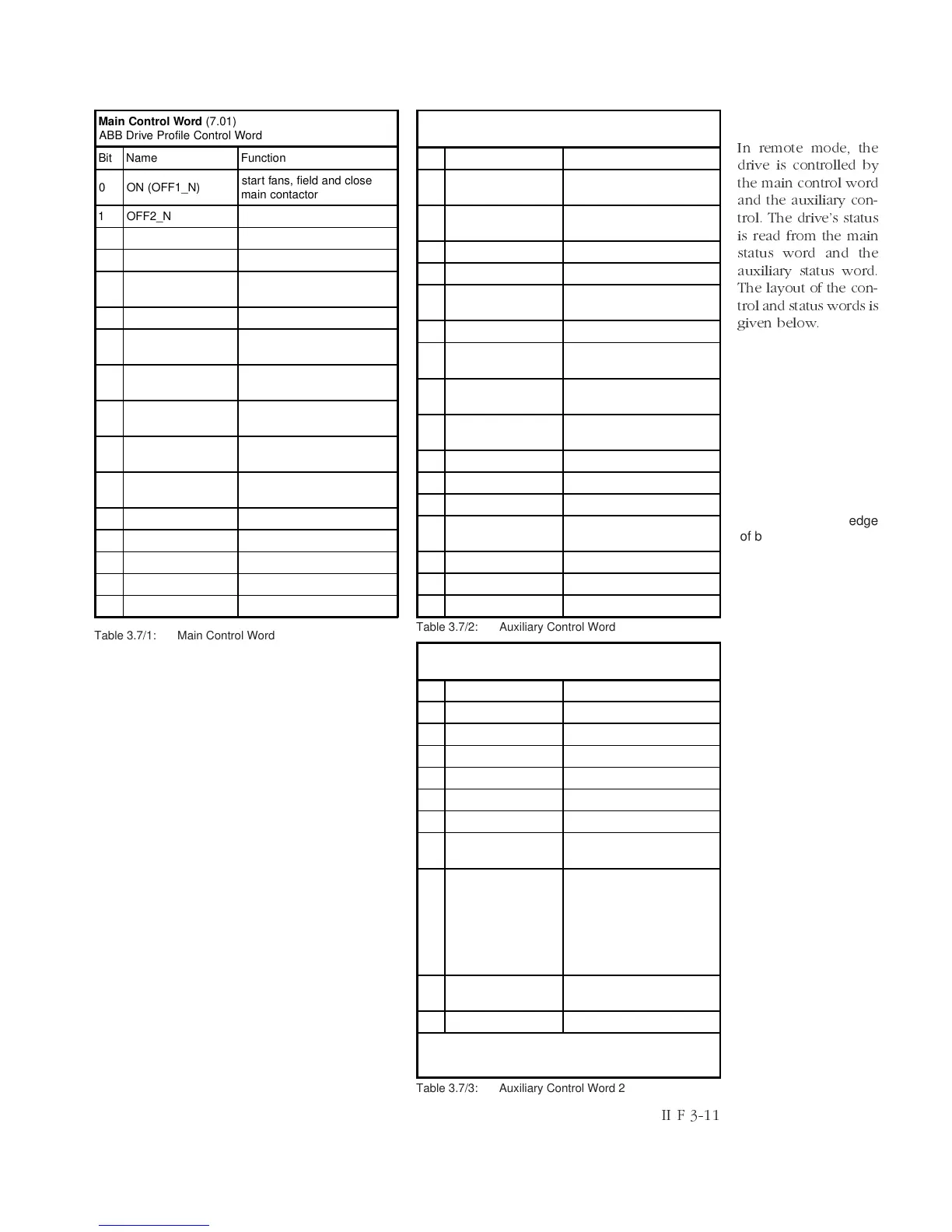
In remote mode, the
drive is controlled by
the main control word
and the auxiliary con-
trol. The drives status
is read from the main
status word and the
auxiliary status word.
The layout of the con-
trol and status words is
given below.
Table 3.7/1: Main Control Word
Table 3.7/2: Auxiliary Control Word
Table 3.7/3: Auxiliary Control Word 2
Main Control Word (7.01)
ABB Drive Profile Control Word
Bit Name Function
0 ON (OFF1_N)
start fans, field and close
main contactor
1 OFF2_N coast stop
2 OFF3_N reserved for emergency stop
3 RUN run with selected reference
4 RAMP_OUT_ZERO
Speed ramp output is forced
to zero
5 RAMP_HOLD Speed ramping is stopped
6 RAMP_IN_ZERO
Speed ramp input is forced
to zero
7 RESET
acknowledge a fault
indication
8 INCHING_1
Constant speed 1 (23.2)
selected
9 INCHING_2
Constant speed 2 (23.3)
selected
10 VALID_CMD
0: Freeze main control word
1: Main control word is valid
11 reserved (reserved)
12 reserved (reserved)
13 reserved (reserved)
14 reserved (reserved)
15 reserved (reserved)
II F 3-11
Note 1
To activate the external
triggering of the datalog-
ger, signal (3.05) must
be selected as trigger
source; the trigger level
should be set between
-30000 and +30000.
The selected edge of the
trigger signal (3.05)
equals the trigger edge
of bit 1 (of 7.02).
Auxiliary Control Word (7.02)
ABB Drive Profile Control Word
Bit Name Function
0 RESTART_DLOG
Restart of data logger (not
available)
1 TRIG_LOGGER
Data logger triggering (see
Note 1)
2 RAMP_BYPASS Speed ramp is bypassed
3 BAL_RAMP_OUT Forcing of ramp output
4
DYN_BRAKE_ON_-
APC
activate dynamic braking
5 reserved (reserved)
6 HOLD_NCONT
Holding of the speed
controller’s integrator
7 WINDOW_CTRL
Torque selector (26.1) is
forced to ADD
8 BAL_NCONT
Forcing of speed controller’s
integrator
9 SYNC_COMMAND synchronising command
10 SYNC_DISABLE synchronising is disabled
11 RESET_SYNC_RDY reset synchronised ready
12 JOGSPEED
Switch speed ramp input to
jog speed (23.12)
13 DIG_OUT4 digital output 4
14 DIG_OUT5 digital output 5
15 DIG_OUT6 digital output 6
Auxiliary Control Word 2 (7.03)
Drive-specific control word of DCS 600 MultiDrive
Bit Name Function
0 DIG_OUT_7 digital output 7
1 DIG_OUT_8 digital output 8
2 DIG_OUT_1 digital output 1
3 DIG_OUT_2 digital output 2
4 DIG_OUT_3 digital output 3
5..7
reserved (reserved)
8 DRIVE_DIR
0: drive direction positive *
1: drive direction negative *
9 SPEED_EXT
0: torque reference
according to min/max
evaluation in torque selector
modes 4 and 5
1: force speed controller
output according in torque
selector modes 4 and 5
10
to
reserved (reserved)
15 reserved (reserved)
* Changes of the commanded drive direction get actice only in
the state RDY_REF; reversal of a running drive by means of this
control bit is not possible.