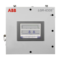
GLA531 Series LGR-ICOS™ Gas Analyzer
Operating Manual
3KXG165002R4201_2021_04
ABB PROPRIETARY INFORMATION 48
The intrinsically safe circuitry of the X-Purge controller supplies electrical power to the analyzer. A fail-safe
detection system signals the X-Purge controller to de-energize whenever a failure is detected, and in turn,
automatically removes electrical power to the analyzer. The electrical power control for this automatic safety
device shown in Figure 35 (CDA purge) and Figure 37 (N
2
purge) is as follows.
• Primary electrical power goes to the overpressure-and-purging control device inside the X-Purge controller
unit.
• Secondary electrical power goes to the analyzer inside the purged enclosure.
The fail-safe detection system is illustrated in Figure 36 (CDA purge) and Figure 38 (N
2
purge): the protective gas
supply for purging is monitored by a low-pressure switch (PS), and two differential-pressure switches (DPS) that serve
as redundant overpressure monitors for the pressurized enclosure. One DPS monitors loss of overpressure inside
the enclosures, and the second DPS detects loss of purge gas flow at the outlet of the enclosure. If any of these
switches senses a failure, electrical power to analyzer is removed.
The other safety function of the X-Purge controller is to provide a timed interval that ensures a minimum of five
volumetric exchanges of a protective gas before electrical power is applied to the analyzer. This time interval is
indicated on the certification plate of the analyzer (see Figure 1). Because this automatic timer is a safety feature, it
cannot be changed or bypassed. Whenever a failure is detected, hard RESET of the timer must be done by cycling
the primary power (turn off main power), and the countdown of the time interval must start from the beginning.
NOTE
Before electrical power can be restored to the analyzer, correct the problem,
switch OFF the incoming electrical power for approximately 30 seconds, then
switch the power back on.
Table 12 below shows a matrix of different conditions that prevent powering the analyzer. Only the condition in the
last row of Table 12 distributes electrical power to the analyzer.
Table 12 Contact States of the Automatic Safety System in X-Purge Controller
PRIMARY
POWER
ENCLOSURE
OVERPRESSURE
OUTLET
FLOW
DPS
CONTACTS
ENCLOSURE AIR
SUPPLY
PS
CONTACT
SECONDARY
POWER
ALARM
CONTACT
ALARM
SIGNAL
NO NO NO OPEN NO OPEN NO OPEN YES
NO NO NO OPEN YES CLOSED NO OPEN YES
NO NO YES OPEN NO OPEN NO OPEN YES
NO NO YES OPEN YES CLOSED NO OPEN YES
NO YES NO OPEN NO OPEN NO OPEN YES
NO YES NO OPEN YES CLOSED NO OPEN YES
NO YES YES CLOSED NO OPEN NO OPEN YES
NO YES YES CLOSED YES CLOSED NO OPEN YES
YES NO NO OPEN NO OPEN NO OPEN YES
YES NO NO OPEN YES CLOSED NO OPEN YES
YES NO YES OPEN NO OPEN NO OPEN YES
YES NO YES OPEN YES CLOSED NO OPEN YES
YES YES NO OPEN NO OPEN NO OPEN YES
YES YES NO OPEN YES CLOSED NO OPEN YES
YES YES YES CLOSED NO OPEN NO OPEN YES
YES YES YES CLOSED YES CLOSED YES CLOSED NO

 Loading...