54
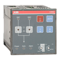
AUTOMATIC CONTROL UNIT, OMD800
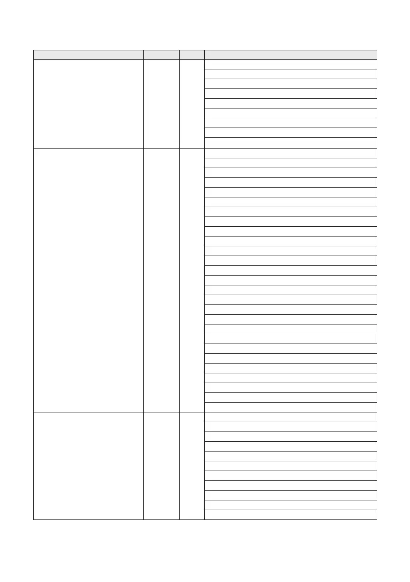
Information of registers, values and access is available in following table:
Register Address R/W Values
REG_CONTROL
0
W
1 = Reset
10 = Change-over switch to position I
11 = Change-over switch to position O
12 = Change-over switch to position II
13 = Test Sequence
21 = Open sec. loads
22 = Close sec. loads
30 = Start generator
31 = Stop generator
REG_ STATUS
40
R
Bits 0-2 = LN1 line status
0 = Voltage OK
1 = No voltage
2 = Undervoltage
3 = Overvoltage
4 = Phase missing
5 = Voltage unbalance
6 = Incorrect phase sequence
7 = Invalid frequency
Bits 3-5 = LN2 status
0 = Voltage OK
1 = No voltage
2 = Undervoltage
3 = Overvoltage
4 = Phase missing
5 = Voltage unbalance
6 = Incorrect phase sequence
7 = Invalid frequency
Bits 6-8 = Switching status
0 = Sequence not required (line used = primary)
1 = Sequence in progress (primary secondary)
2 = Sequence completed (line used = secondary)
3 = Sequence rev in progress (secondary primary)
4 = Sequence failed
Bit 9 = Generator status
0 = Stopped
1 = Started
REG_ALARMS
54
R
0 = No Alarms
Bit 0 = Open 1 Failure
Bit 1 = Open 2 Failure
Bit 2 = Disconnect SL Failure
Bit 3 = Close 1 Failure
Bit 4 = Close 2 Failure
Bit 5 = Connect SL Failure
Bit 8 = Force manual (handle attached)
Bit 9 = External fault
Bit 10 = External alarm
Bit 12 = Generator alarm