53
AUTOMATIC CONTROL UNIT, OMD800
AUTOMATIC CONTROL UNIT, OMD800
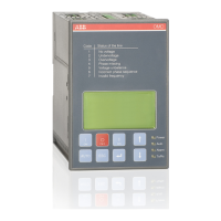
Test Sequence
Test Sequence carries out the automatic switching sequence with delay times and generator control.
The OMD800 has to be in manual mode to start the Test Sequence. When user starts the Test Sequence
the device blinks LEDs (Power, Auto, Alarm) twice and returns to default page to show the status of the
change-over switch, delay times and generator. If the change-over switch is in position I, normal
switching sequence with generator start is executed. If in position O or II, back switching sequence is
executed and generator stopped. Test Sequence can be interrupted by pressing the AUTO key. Auto
LED blinks during Test Sequence.
Diagnostics
Counters
Generator Control
Test Sequence
5/6
SW: 2A1 SN: 0
LN1:
230.0 V
50.0 Hz
LN2: 1
0.0 V
0.0 Hz
L
LN1 LN2
KA00254
Figure 7.52 Test Sequence carries out the automatic switching sequence, the Auto LED blinks during
Test Sequence
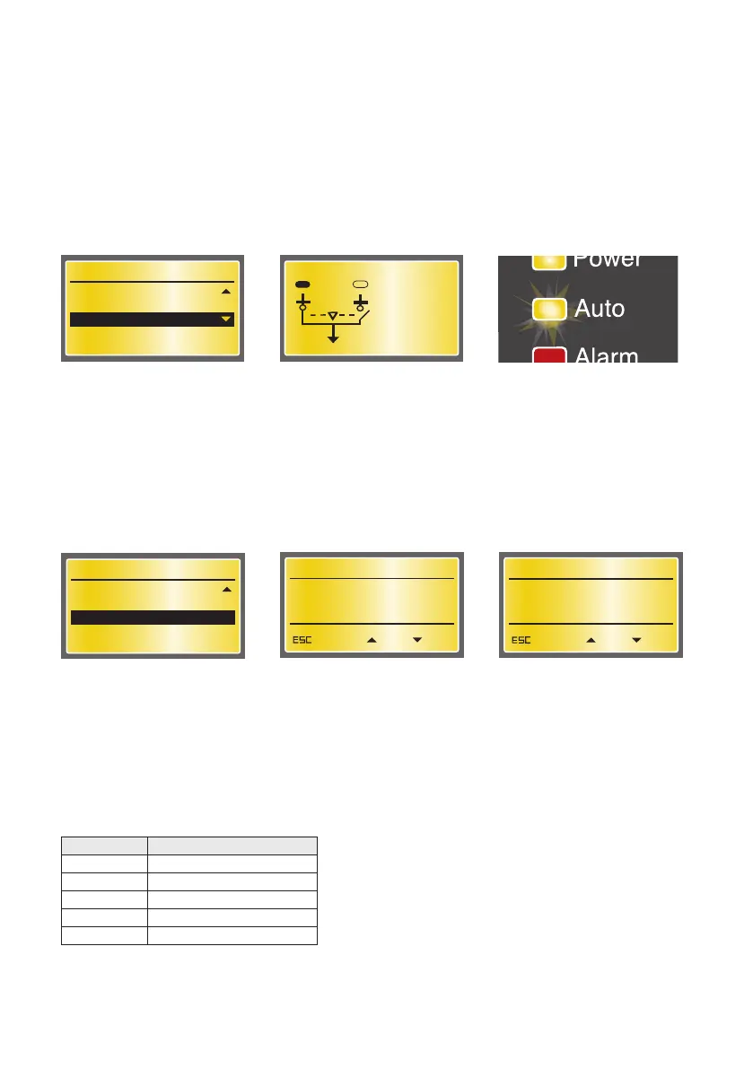
Secondary Loads
On this page the user can connect or disconnect the secondary loads if the Secondary Load –parameter
is set in System Configuration subpage (see the selection of “Secondary Load” on Section 7.2.2.3). Con-
nect and Disconnect commands are given with UP and DOWN arrow keys. Return back to Diagnostics
menu by pushing the ESC key.
Diagnostics
Generator Control
Test Sequence
Secondary Loads
6/6
SW: 2A1 SN: 0
Secondary Loads Control
Conn.
SEC. LOADS DISCONNECTED
Disc.Return
Secondary Loads Control
Conn.
SEC. LOADS CONNECTED
Disc.Return
Figure 7.53 Secondary Loads page, secondary loads can be connected and disconnected
7.2.3 OMD800 communication via Modbus
Monitoring, configuration and control are possible via OMD800 Modbus communication interface.
Configuration and control are enabled by Local/Remote parameter (see the selection of “Local/
Remote” on Section 7.2.2.4). The following Modbus functions are supported:
Function Name
3 (0x03) Read Holding Registers
4 (0x04) Read Input Registers
6 (0x06) Write Single Register
16 (0x10) Write Multiple Registers
17 (0x11) Report Slave ID
Table 7.12 Supported Modbus functions