2TLC172287M0201 Rev B 15 www.abb.com/jokabsafety
2015-09-17
The formula to get D
sr
for a Type 4 AOPD is the following:
D
sr
(m) = 0.15 for operating distance < 3 m
D
sr
(m) = 0.5 × operating distance (m) × tan (2) for operating distance 3 m
Warning! If the reflecting surface is the floor, the calculated D
sr
can be less than the correct height to the floor that
still must be respected.
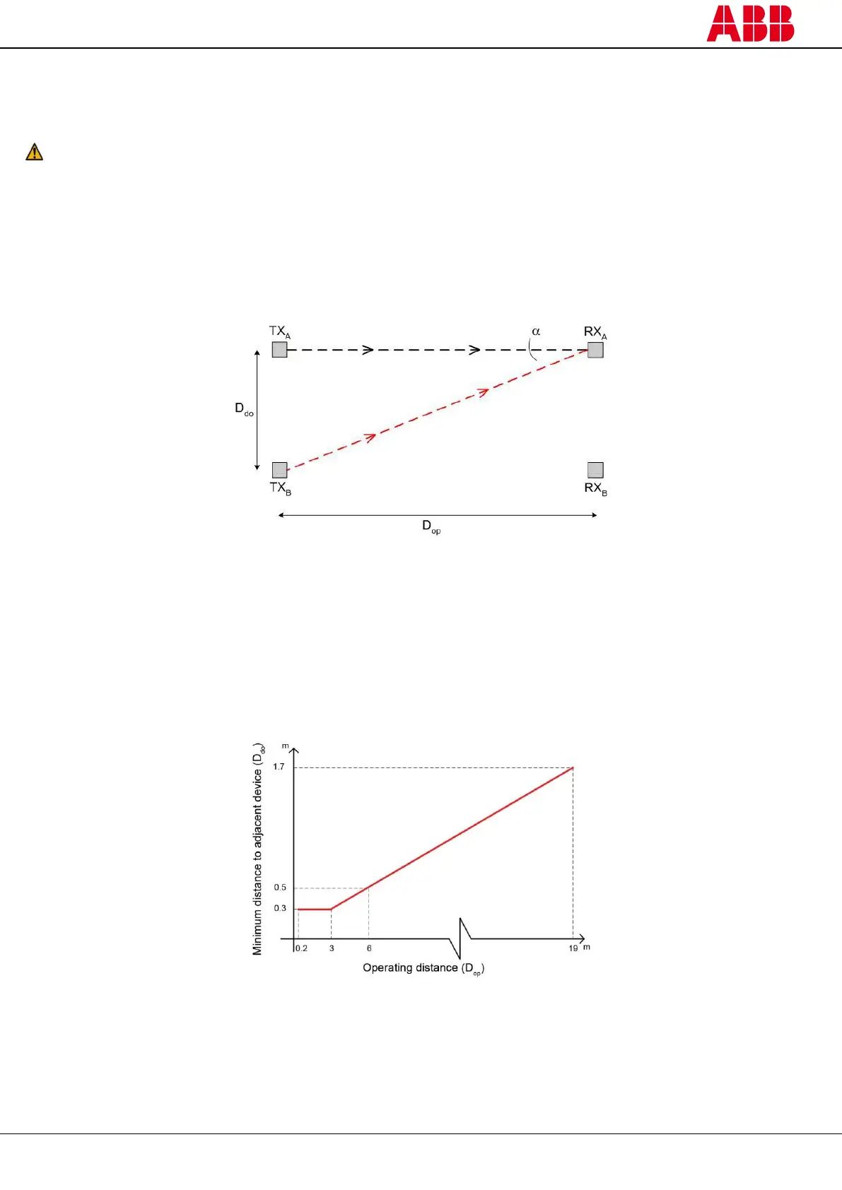
3.2.3 Minimum distance between adjacent devices
When several AOPDs must be installed close to each other, the transmitter of one device must not interfere
hazardously with the receiver of the other device.
The TX
B
interfering device must be positioned outside a minimum D
do
distance from the axis of the TX
A
– RX
A
transmitter-receiver couple, see figure below.
Figure 11 – Distance between adjacent devices
This minimum D
do
distance depends on:
the operating distance between transmitter (TX
A
) and receiver (RX
A
),
the effective aperture angle of the AOPD (EAA):
For a Type 4 AOPD, EAA
MAX
= 5° (α = ± 2.5°).
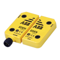
The diagram below shows the distance to the interfering devices (D
do
) based on the operating distance (D
op
) of the
couple (TX
A
– RX
A
) for a Type 4 AOPD.
Figure 12 – Minimum distance to an adjacent device as a function of the operating distance
The formula to get D
do
for a Type 4 AOPD is the following:
D
do
(m) = 0.3 for operating distance < 3 m
D
do
(m) = operating distance (m) × tan (2) for operating distance 3 m