2TLC172287M0201 Rev B 20 www.abb.com/jokabsafety
2015-09-17
5 Electrical connections
All electrical connections to the transmitter and the receiver are made through a male M12 connector located on the
lower part of the two units, a M12 4-pole connector for the transmitter and a M12-8 pole connector for the receiver.
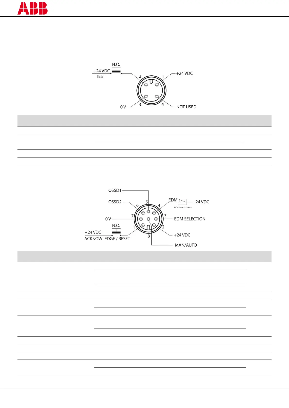
5.1 Transmitter (TX)
NO contact to +24 VDC if to be used
Not connected or 0 V if not to be used
1
Colors according to ABB Jokab Safety standard cables
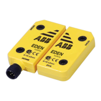
5.2 Receiver (RX)
Auto. Reset with no function
Auto. Reset with Acknowledge
function or Alignment mode
NC contact of a force-guided
relay
Function not used/deactivated
Safety control module for ex.
Safety control module for ex.
1
Colors according to ABB Jokab Safety standard cables