2TLC172287M0201 Rev B 9 www.abb.com/jokabsafety
2015-09-17
2.4 Minimum installation distance
Warning! The information given in this chapter shall be considered as an overview. For correct positioning, please
refer to the latest version of the complete standard EN ISO 13855 ”Safety of machinery – Positioning of safeguards
with respect to the approach speeds of parts of the human body”.
The safety device must be positioned at a distance that prevents a person or part of a person to reach the hazard
zone before the hazardous motion of the machine has been stopped by the AOPD.
According to EN ISO 13855:2010, the minimum distance to the hazard zone is calculated using:
S = (K × T) + C
S Minimum distance (mm) between safeguard and hazard zone.
K Approach speed of body parts towards the hazard zone (mm/s). See below for values.
T Overall system stopping performance (s) with T = T1 + T2, where:
T1 = response time of the AOPD (s).
T2 = stopping time of the machine, including the response time of the safety control system (s).
C Intrusion distance (mm). C depends on the resolution d and the position of the detection zone. See below.
2.4.1 Vertically assembled AOPD
The minimum distance S for a vertically assembled AOPD is determined in three steps:
a) Calculation of the minimum distance for reaching through the detection zone, S
RT
.
b) Calculation of the minimum distance for reaching over the detection zone, S
RO
.
c) Comparison of S
RT
and S
RO
. The minimum distance S is the greater of the two.
NB: If access to the hazard zone by reaching over the AOPD can be excluded, e.g. by the provision of guards or other
protective measures, steps b) and c) are not necessary.
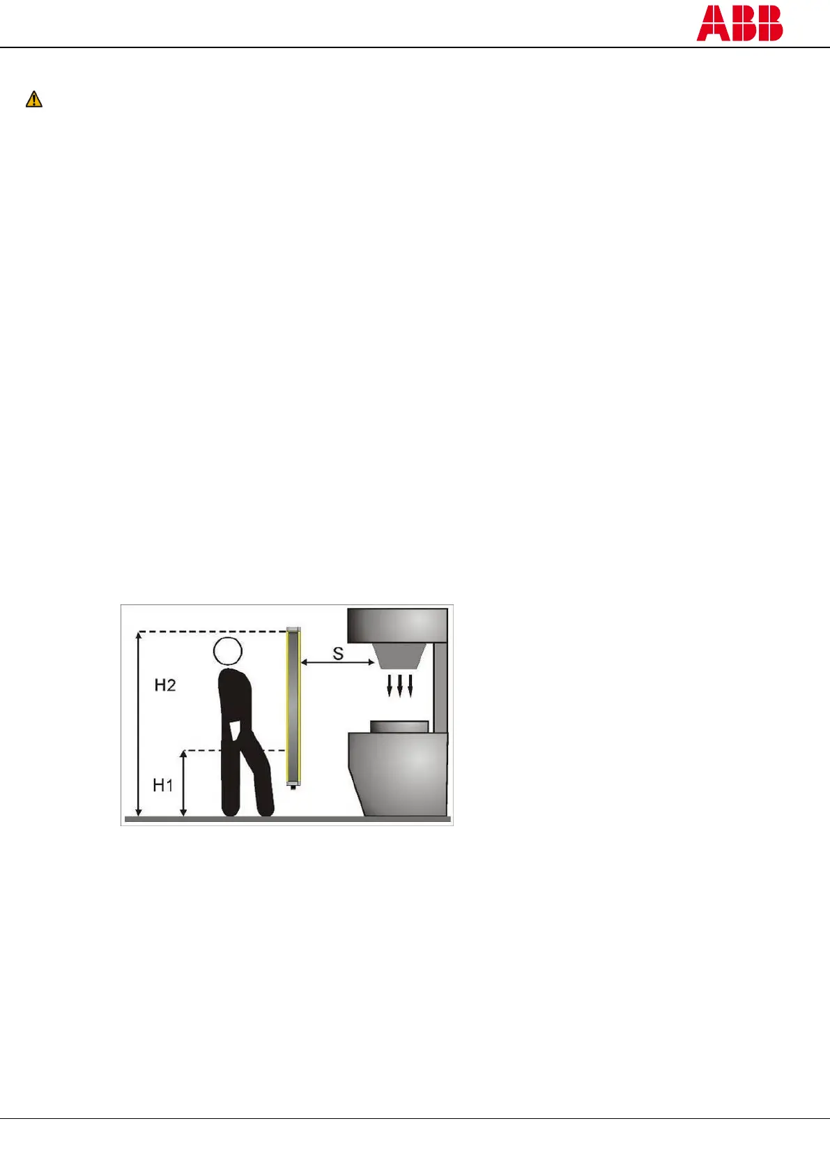
Figure 3 – Minimum distance for a vertically assembled AOPD
S = minimum distance in mm
H1 = height of the lowest beam
H2 = height of the uppermost beam
H1 ≤ 300 mm*
H2 ≥ 900 mm
* 400 mm can be used for 2 beams
when the risk assessment allows it.
a) S
RT
= (K × T) + C
RT
C
RT
= 8 × (d-14) mm for devices with a resolution d ≤ 40 mm
C
RT
= 850 mm for devices with resolution d > 40 mm
NB: Floating blanking has an influence on the resolution. Please check the correct value.
If the resolution is ≤ 40 mm, use first K = 2000 mm/s.
In this case, the minimum value of S = 100 mm, except in single/double break mode with a resolution
d > 14 mm when S must be > 150 mm.
If the resolution is > 40 mm or if the previously calculated value of S is > 500 mm, use K = 1600 mm/s. In
this case, the minimum value of S = 500 mm.